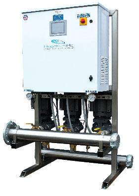
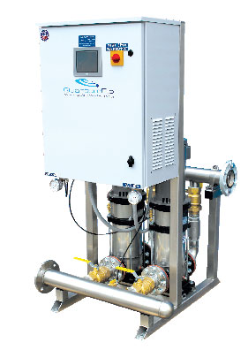
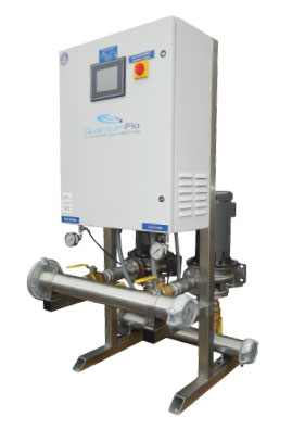
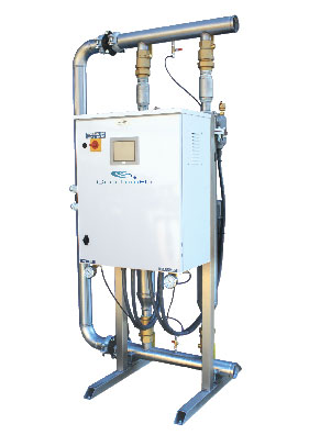
ANSI/ASHRAE/IES, Standard 90.1 – 2010; also referred to as the “Energy Standard for Buildings,” has created the need for innovation in many industries. In the world of pressure booster control, it can be argued that in recent history there has not been a more seminal event than the impact of this new standard. Standard 90.1 rewrites the laws governing water pressure control and delivery. This design change affects the control structure and, in some cases, the location of pressure control devices. As a result, QuantumFlo needed to develop a solution that did not move these controls, but instead utilized advanced system technology to simulate the same effect. QuantumFlo’s GreenFlo™ logic is a new and innovative algorithm that began shipping in January 2014 on all QuantumFlo packaged systems in order to fully comply with the newly adopted standard.
[h2]OVERVIEW[/h2]
Variable speed pressure boosting has clearly become the de-facto pumping control standard. Manufacturers are required to establish a well-planned direction on how these controls are used to optimally reduce energy consumption within a project site.
ANSI/ASHRAE/IES 90.1 (Standard 90.1) took this energy efficiency even further by considering all infrastructure, machinery, lighting, etc. within the building in order to facilitate a sustainable design that considers all disciplines of construction. It is a directive to architects and mechanical and electrical engineers to produce more LEED compliant and sustainable structures that optimize the energy usage for lower carbon footprints.
10.4.2 Service Water Pressure Booster Systems.
Service water pressure booster systems shall be designed such that:
- One or more pressure sensors shall be used to vary pump speed and/or start and stop pumps. The sensor(s) shall either be located near the critical fixture(s) that determine the pressure required, or logic shall be employed that adjusts the set point to simulate operation of remote sensor(s).
- No device(s) shall be installed for the purpose of reducing the pressure of all of the water supplied by any booster system pump or booster system, except for safety devices.
- No booster system pumps shall operate when there is no service water flow.
[h2]CHALLENGE[/h2]
The most significant challenge for QuantumFlo regarding Standard 90.1 is under Section 10, “Other Equipment,” specifically 10.4.2, “Service Water Pressure Booster Systems.” GreenFlo™ directly addresses the challenge outlined in point a.
The inclusion of 10.4.2a is monumental for constant pressure booster design, which has always maintained that the discharge pressure of the system must never change. Now Standard 90.1 states that the control point (pressure sensor) should be moved to the top of the building. This entails that the booster pressure will adjust in consonance with system demand minus the friction loss in the piping run. The booster system set point will now change when it should have never changed in the past according to the flow rate of the system. This means that as the system begins to reduce in gallons per minute, the set point will now change due to decreased friction-loss in the piping at the reduced flow.
In the past, the designer would add up the following conditions to arrive at a booster set point:
- Static height of the plumbing system in feet, converted to PSI
- Residual pressure in PSI required at the remote fixture (top of system)
- Friction losses at 100% design flow, to deliver that water to the remote fixture
Since the friction loss (Item 3) changes as the flow rate changes, a rise in residual pressure would occur at lower flows causing the pressure at the top of the system to change according to the piping friction at the actual flow rate. This causes a slight rise in pressure at the roof when the pump is at or near its no-flow condition. This is why some manufacturers would suggest that hydro-pneumatic tanks mounted at the roof could be employed to store this “extra” pressure.
…or logic shall be employed that adjusts the set point to simulate operation of remote sensor(s).
Standard 90.1 has determined that the level of inefficiency caused by this recovered friction is sufficient enough to require the pump to be further reduced in speed. Therefore, a remote-mounted sensor would provide for a pressure which never changes at the roof of the building due to the sensor being located there. It has been referred to as the “80/20 Rule” for boosters. Eighty percent of the time a typical water pressure booster is at twenty percent capacity or less. If the sensor is now moved to the roof there is no longer a pressure change as it will track only the target pressure required there. Without this pressure change (recovered by the variable frequency drives, VFDs) these tanks now become useless in remote mount applications as they rely on the former pressure change that no longer exists. Without pressure change, there is no water storage.
[row]
[col width=”six”]

[/col]
[col width=”six”]

[/col]
[/row]
Many manufacturers have to comply with this new standard by advising the plumbing contractor that the sensor provided (loose) by them must be mounted and wired by a third-party trade (electrical or controls contractor). This added step creates a substantial additional cost to the plumbing contractor as he will need to hire an electrician to complete this work. This is not a good solution to the problem as most packaged boosters are built and pre-engineered as complete plug and play systems. Field installed components reduce the reliability.
[row]
[col width=”six”]

[/col]
[col width=”six”] [/col]
[/row]

[h2]SOLUTION[/h2]
The best way to address the control challenge of Standard 90.1 is through the application of simulation logic. QuantumFlo’s GreenFlo™ is pre-engineered algorithm in their pump systems. There is no advantage to shipping a machine that relies on the additional labor and expense of other trades to wire a remote sensor back to the controller, usually at the bottom of the building. This complicates the job and injects an additional contracting discipline into a plumbing system that should work correctly out of the box.
GreenFlo™ is the solution to the problem of pretesting equipment as if it were already installed on the site before it is shipped. This algorithm is built into the current iQFlo™ software package and is completely automatic in operation. The “GreenFlo™ Mode Indicator” appears on the main screen to inform the user when the mode is active. This is an icon that shows to the immediate left of the QuantumFlo logo on the main system screen.
When the system is in a low flow condition, rather than monitoring the remote sensor at the roof, GreenFlo™ is reading energy consumption through a variety of values streaming from the variable frequency drive in real time. The circuit activates at low flow conditions and changes the set point according to the pressure entered in the GreenFlo™ mode activation screen. The system resets to this new set point and when the demand rises above these conditions, it reverts back to the design set point. By using a software-based solution, the system can continue as a true pre-engineered product that has been factory tested at simulated jobsite conditions.
When the GreenFlo™ icon is visible, this verifies to the user that the system is operating in full compliance with Standard 90.1 through GreenFlo™ in lieu of the remote mounted transducer, and it still complies with the code which reads:
GreenFlo™ is completely field adjustable by the commissioning agent using the “virtual toggle” and set value. Since no plumbing system is the same, this allows the user to adjust the amount of friction to suit any project need in the field.
[h2]SUMMARY
Pump system manufacturers have two choices to modify their systems to be in compliance with Standard 90.1. They can provide a transducer, shipped loose, to be mounted at the remote point in the field by a contractor, or they can provide an algorithm within the system that simulates the same effect. Since QuantumFlo is streaming data at 115,000 bits per second, GreenFlo™ takes advantage of this superior logic strategy and makes compliance with Standard 90.1 invisible to the plumbing contractor. GreenFlo™ requires no additional equipment, is available at no cost increase to the plumbing contractor as logic is standard in all QuantumFlo systems, and is fully automatic in operation.
The goal of QuantumFlo as a manufacturer is to provide the contractor with a product that would not add any additional cost in the effort of meeting the requirements of Standard 90.1 by creating a built-in algorithm like GreenFlo™ instead of requiring other external components to be installed.
As the leader in pressure boosting and controls technologies, QuantumFlo is committed to providing innovative leadership as the demands of the industry dictate. GreenFlo™ is another way they provide contractors and consultants with products that create opportunity through energy efficiency and sustainable design, superior quality of workmanship and a commitment to industry leadership.
■ ■ ■
[divider]
ABOUT THE AUTHOR
David Carrier is chief executive officer of QuantumFlo, Inc., a leader in the manufacturing and distribution of advanced, variable speed controlled, packaged pump systems for commercial plumbing, HVAC, municipal, irrigation and industrial market applications. He can be reached at 386.753.9702 or via dave@quantumflo.com. For more information, visit www.quantumflo.com.
MODERN PUMPING TODAY, May 2014
Did you enjoy this article?
Subscribe to the FREE Digital Edition of Modern Pumping Today Magazine!


