

One of the major pump OEMs had invited Mechanical Solutions, Inc. to resolve an occurrence of multiple pump driveshaft failures for one of their most important customers, a well-established international ore mining company. The operation of the relatively new pump systems at the mining company’s raw water pumping station in East Africa frequently had been accompanied by objectionable vibration levels. Recently two of the three large pump systems had sustained catastrophic failures, which had occurred roughly one month apart. What phenomena had caused both of the driveshafts to fail in rapid succession? And once its true source was identified correctly, what actions and how much effort would be required to correct this acute machinery problem permanently?
Typically this station pumped river water for slurry production through a pipeline to a separate mining and processing facility, which was located several miles away from the station. However, the lack of pumping capacity temporarily had shut down the whole ore mining operation. The unanticipated outage had penalized the facility’s owners upwards of $100,000 per week in lost production revenue. Out of necessity the company planned to restart the mining operation without delay. Unfortunately, the prior efforts of others had failed to identify the true source of the broken pump driveshafts, which placed the operation at considerable risk. Therefore, the objectives of this testing project were to identify the root cause of the driveshaft failures, and to devise a practical solution that would eliminate the recurrence of the costly and potentially dangerous pump system breakdowns.
THE STATION HAD RESUMED OPERATION
After MSI arranged a detailed evaluation plan, two MSI engineers journeyed to the remote site with an array of comprehensive instrumentation, to perform extensive vibration testing of the pump systems. In each of the three pump systems, a 1200 horsepower diesel prime mover was connected to a large vertical turbine pump through a welded, hollow driveshaft and a 1:1 right angle gearbox.
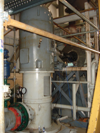
Figure 1: One of the three pump systems at the station is depicted in the figure, viewed in the direction toward the prime mover. Because the coupling guard had been removed to perform the repairs, the massive driveshaft which connected the prime mover and the right angle drive is visible.
Figure 1 shows one of the three pump system installations at the station. Each of the multistage pumps when in operation moved over 24,000 cubic feet (680 cubic meters) of water per hour, and featured a column pipe which extended approximately 40 feet (12 meters) below grade. To satisfy the unique geometric and dimensional requirements of these particular installations, the massive steel driveshafts which connected the prime movers to the pump gearboxes had been welded together from smaller subsections, and they also had been equipped with large constant velocity joints at both ends. Notably, both of the mechanical failures had occurred at the locations of the welded joints in the fabricated driveshafts. One of the two massive pump system driveshafts which had failed is depicted in figure 2.
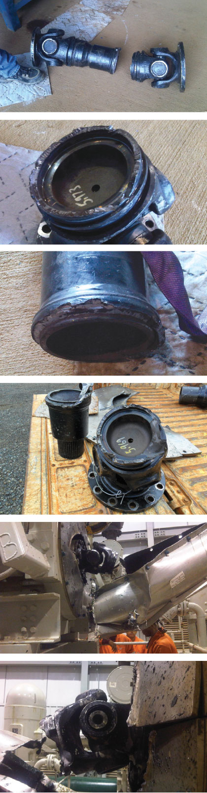
Figure 2: The figure presents several views of one of the two failed driveshafts from the pumping station. The welded, hollow construction of the driveshaft clearly is evident, as is the complete failure through the cross section of the driveshaft. In the upper left hand view, the massive size of the driveshaft also is apparent.
The pump systems at the station immediately had been returned to service by the mining company, once the replacement driveshafts were fabricated and installed. At the suggestion of others, supplementary structural steel bracing, steel cladding, and steel plates had been welded to the existing pump system support structures. Considerable amounts of extra grout also had been put in, and this included the packing of the new voids in the structures which were formed by the addition of the cladding. Based on the continued elevated vibration which was present as the pump systems operated, however, the modifications apparently had little influence on the actual machinery problem that was at hand. It also was evident that the diesel prime movers ran very roughly, and in fact instances of backfiring were observed relatively frequently while the pump systems were in operation.
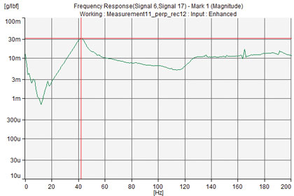
Figure 3: The figure shows a plot of typical experimental modal analysis (EMA) frequency response test data that was recorded from one of the pump shafts, in the direction perpendicular to the pump discharge piping. The test data indicates that the pump shaft has a natural frequency of 42 Hz, which is adequately separated from the 1x rpm speed, 30.3 Hz, but close to 1½x rpm.
COORDINATED TESTING AND ANALYSIS WAS PERFORMED
Sufficient data was recorded at the test site over several days to accomplish a competent diagnosis of the puzzling machinery problem. Experimental modal analysis (EMA) testing was performed to identify the actual structural natural frequencies and mode shapes of the three pump systems. Using accelerometers, the response frequencies of vibration were recorded both parallel and perpendicular to the pump discharge piping. The data was logged at many locations on the gearbox top, the column pipe, the pump shaft, and the top of the diesel prime mover, and also in the vertical direction at the top of the gearbox.
Figure 3 presents a typical plot of the EMA data, which was recorded at the pump shaft of one of the pump systems at the station. Also, the separation margins in percent between these natural frequencies and the maximum response frequencies of 1x rpm and 1.5x rpm speeds of both the pump and the prime mover were calculated and reviewed.
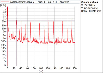
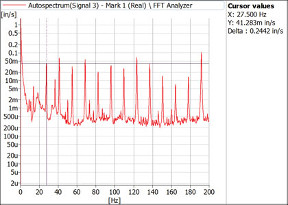
Figure 4: Illustrated in the figure are the ODS plots of the data which was recorded at the top of one of the pump system’s diesel prime movers. The FFT spectra at the top, for the direction parallel to the crankshaft and the pump discharge piping, shows a response of 0.067 in/s rms at 1x rpm, and of 0.322 in/s rms overall. The FFT spectra for the perpendicular direction, bottom, shows a response of 0.041 in/s rms at 1x rpm, and of 0.244 in/s rms overall. These values are considered elevated, but do not by themselves necessarily indicate a serious problem.
At strategic locations on each pump system, the operating deflection shape (ODS) test data was acquired during steady state operation, and all of the test data points were tied to consistent, three dimensional, spatial reference coordinates. In the directions both parallel and perpendicular to the pump’s discharge piping, Fast Fourier transform (FFT) spectra were recorded at roughly the same locations on the pump systems as were the EMA data. For each pump system, the recorded overall vibration amplitudes, as well as those at 1x rpm of the pump and at 1.5x rpm of the prime mover, were summarized and compared. Figure 4 illustrates as an example typical plots of the ODS data, which was recorded at the top of the prime mover of one of the pump systems at the station.
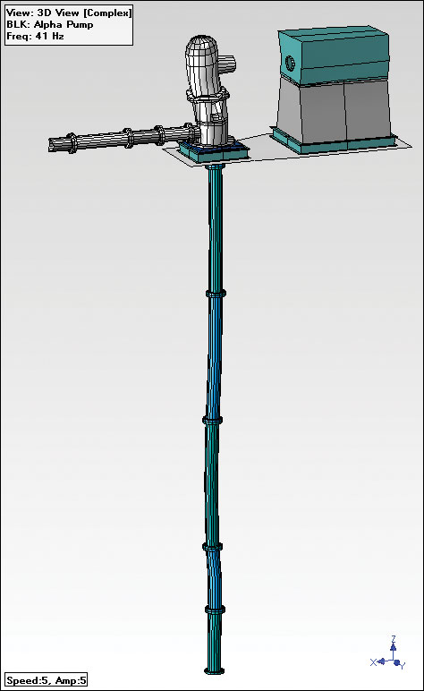
Figure 5: A still frame from an ODS animation file for one of the pump systems is depicted in the figure. At a vibration frequency of 41 Hz, the right angle gear drive at the top of the pump has been displaced from the vertical, in the direction parallel to the pump discharge piping and the driveshaft. Clearly visible in the ODS animation, this movement confirmed the existence of the large oscillating compression load in the driveshaft, should the driveshaft splines not slide.
Further, the recorded ODS test data was processed with proprietary computer software, to create graphical animation files of the vibration mode shapes and torque oscillations of the pump systems. Each resulting ODS file was a computer animation that displayed in an exaggerated manner the amplitude and also the phase of each portion of the pump system’s structure. The ODS files were created for each of the pump system’s key vibration frequencies. Shown in figure 5 is a plot of a still frame from the ODS animation file for one of the pump systems.
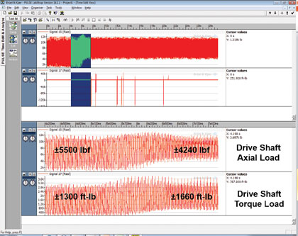
Figure 6: Dynamic strain gage data which was recorded from the driveshaft of one of the operating pump systems appears in the figure during a load transient, where the bottom two plots are magnifications of the highlighted bandwidth in the overall data plots which appear in the top half of the figure. The test data displays the unusually large oscillating longitudinal load that existed, which when combined with the oscillating torsional load created an environment that would promote crack growth in the driveshaft.
Strain gages in conjunction with RF telemetry systems were attached to the driveshaft of one of the pump systems. During the pump system’s operation, the strain gage outputs were monitored and the axial and torque loads on the driveshaft were calculated continuously from the recorded data. Figure 6 illustrates a plot of this data for one of the pump systems. Working in parallel, engineers back at the U.S. office evaluated the test results, and also performed a finite element analysis (FEA) of the welded driveshaft design using the measurements that were taken directly at the pumping station.
A LOOK AHEAD
In next month’s conclusion, we will present how analysis of the data unlocked the solution to the puzzle and the practical resolution to prevent the damaging combined mechanical stress condition from recurring in any of the three pumping system driveshafts. ◆
Maki Onari is manager of turbomachinery testing and Juan Gamarra is senior staff engineer at Mechanical Solutions, Inc. (MSI). MSI performs consulting and R&D, as well as provides design, analysis and testing services for organizations throughout the US and overseas. MSI is proud of its outstanding track record in solving some of the world’s most difficult technical problems. For more information, call 518.320.8552 or visit www.mechsol.com.
____________________________________________
MODERN PUMPING TODAY, June 2015
Did you enjoy this article?
Subscribe to the FREE Digital Edition of Modern Pumping Today Magazine!
![]()
Curing a Raw Water Pumping Facility’s Unremitting Driveshaft Failures: Part 1 of 2
