


Pumps that utilize a diaphragm for their mechanical force have been used since the mid-nineteenth century, and continue to be utilized in modern pumping applications because of their simplicity and effectiveness. Over 150 years of innovation and technical advances in both diaphragm profiles and elastomeric material sciences have secured their continued utilization across a range of pumping and reciprocating applications. The design and utilization of diaphragms in pumping applications is a vast topic. Despite this broad scope, at Gallagher Fluid Seals, application engineers approach the design and manufacturing of diaphragms through a step-by-step process that results in the best diaphragm design, with the most appropriate material, constructed in a manner that optimizes manufacturability and cost. Freudenberg-NOK Sealing Technologies are invaluable partners to Gallagher Fluid Seals in this process, and are amongst the foremost experts on diaphragms in the world.
An elastomeric diaphragm is a versatile dynamic seal that eliminates many of the limitations of other sealing methods. They do not leak, offer little friction and can be constructed for low pressure sensitivity. With proper material consideration, diaphragms can seal over a wide temperature and pressure range without maintenance or lubrication.
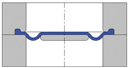
Figure 1: Convoluted diaphragm
DIAPHRAGM DESIGN CHECKLIST
1. Environmental, Functional and Material Considerations
What is the basic function of the diaphragm? Is it acting as a regulator with pressure from one side, or as a pump with pressure from both sides? Very important distinctions distinguish diaphragms for control, switching, accumulation or pumping applications. What are the environmental conditions? Specifically what temperature, humidity and media is the diaphragm exposed to?
After establishing the functional criteria, decisions can be made regarding the material for the diaphragm elastomer itself, as well as any reinforcing-fabric layers that may be required to increase the structural performance of the diaphragm. These material considerations must be based on the media being sealed or pumped. Is it a passive material such as air or water, or an aggressive material such as a solvent or petrochemical?
Material selection typically requires the expertise of the supplier. Specifying the best choice of materials not only ensures the longest possible life of the diaphragm, but can often avoid unnecessary costs by not “over-designing.” The elastomer choice is critical when considering the environment in which the part will operate, and will often override manufacturability considerations. Relevant elements include: chemical contact, abrasive hardware or medium, applied loads and health or federal regulations.
What are the pressure requirements and is does it ever deviate or reverse from those? Depending on the PSI levels, different secondary materials integrated into the diaphragm are required. Typically PSI under 5 does not require fabric reinforcement, and between 5 and 10 it is application dependent. PSI above 10 almost exclusively requires fabric reinforcement. What are the maximum and minimum operating temperatures? What is the duration at its maximum temperature? Information surrounding the cycle rate and pumping volume dictate the construction and shape elements that complete the design of the diaphragm.
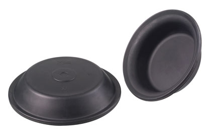
Figure 2
2. Construction and Shape Elements
A primary goal of the design process is to consider the construction method of the diaphragm at the earliest stage possible. A layer of reinforcing material molded to the elastomer, or a layer of coating on one or both sides of the diaphragm can clearly add significant cost to the component. The decision to use a coating on one or both sides of the diaphragm is dependent on the pressure, media, and stroke length of the piston. It should be noted that the when considering stroke length it is the relative stroke length of the piston head to the diameter of the diaphragm that matters, not any specific stroke length value. The elastomer forms a sealing barrier between the system pressure and the porous fabric, enabling the diaphragm to convert pressure into a mechanical force.
primary goal of the design process is to consider the construction method of the diaphragm at the earliest stage possible. A layer of reinforcing material molded to the elastomer, or a layer of coating on one or both sides of the diaphragm can clearly add significant cost to the component. The decision to use a coating on one or both sides of the diaphragm is dependent on the pressure, media, and stroke length of the piston. It should be noted that the when considering stroke length it is the relative stroke length of the piston head to the diameter of the diaphragm that matters, not any specific stroke length value. The elastomer forms a sealing barrier between the system pressure and the porous fabric, enabling the diaphragm to convert pressure into a mechanical force.
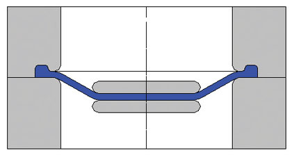
Figure 2: Dished diaphragm
Pressure or aggressive media on one side should use a one side coated part, and could use a two side coated part. With pressure on two sides, a one side coated part will always fail and must use a two side coated part. A short to medium stroke length will allow for a one or two sided coat, but a longer stroke length must use a one side coated design because of the additional flexibility required. The mating hardware finish is another consideration in the construction elements of a diaphragm in that a rough surface will erode the fabric reinforcement to the point of seal failure.
The specific geometric profile of the diaphragm is application dependent, but more often than not, the primary consideration is stroke length. A short stroke will allow for a flat or die cut diaphragm, a low convoluted or shallow draw profile. A medium stroke will typically call for a shallow draw, convoluted or drop center. A long stroke requires a deep draw or top hat. Figures 1 through 4 are images and illustrations of each profile (source: FNST ©2009).
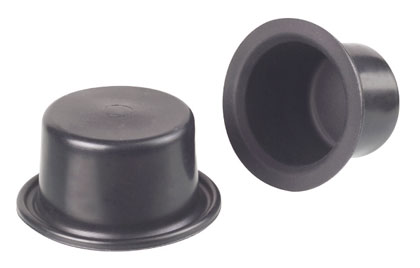
Figure 3
3. Application Properties and Hardware Considerations
Cycle rate and expected cycle life of the diaphragm must be established. These values are tested for confirmation during the prototype phase. How will the diaphragm device be assembled? Options include a bolted piston and flange, a riveted piston with a flange, spin crimp or swage, or a sonic weld. Requisite hardware is made from either injection molded plastic, stamped or formed metal, or a machined plastic or metal. Additional hardware considerations include the presence of return springs, positive stops, the piston design, and care over time of the diaphragm.
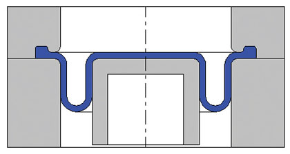
Figure 3: Rolling diaphragm
Each of these considerations eliminates various design options, and the optimal diaphragm design begins to emerge. Final considerations include any unique specifications or requirements such as UL, or FDA compliance. While typically material in nature, these certifications can require extensive testing and validation to attain, and as such can add significant cost to the overall diaphragm application.
DIAPHRAGM INSERTS
Bonded to the diaphragm during the molding process, diaphragm inserts provide enhanced connectivity, facilitating the assembly process and conserving costs. Benefits of the inserts include ease of assembly of the diaphragm, built-in piston-area support, reduction of SKU’s, and a well centered attachment point. Typical metal insert materials include stainless steel, aluminum and brass, and plastic materials are typically either fiberglass-filled polyamide or PEEK.
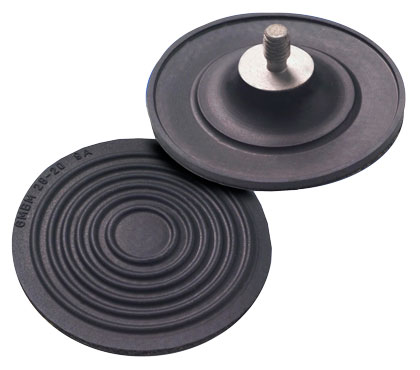
Figure 4
PRODUCT DESIGN AND VALIDATION
Engineers at Gallagher Fluid Seals and our partners at Freudenberg-NOK Sealing Technologies design every custom diaphragm to your specifications, and validate the design before manufacturing begins. Virtual validation techniques, specifically FEA capabilities, allow for decreased manufacturing costs and optimal design. These rigorous procedures give the customer the benefit of exact product design, shorter development times with lower costs.
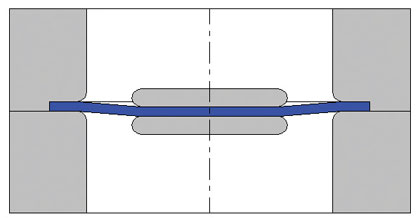
Figure 4: Flat diaphragm
Testing capabilities to validate in-use performance include: Hot endurance testing, Hot steam, tensile strength, cold liquid, hysteresis, bending fatigue strength, permeation, as well as any customer driven application testing process.
ABOUT THE AUTHOR
Christopher Gallagher is the marketing director at Gallagher Fluid Seals, a fifty-eight-year-old ISO certified distributor of fluid seals in King of Prussia, Pennsylvania. For more information, call 800.822-4063 or visit www.gallagherseals.com.
MODERN PUMPING TODAY, July 2014
Did you enjoy this article?
Subscribe to the FREE Digital Edition of Modern Pumping Today Magazine!®