Packaged pump systems are gaining in popularity because they include benefits such as space-savings design, simplified installation, single-source responsibility and advanced control options with the ability to communicate with other systems.
The term “packaged” means that all the components needed for the pump system are pre-engineered and mounted on a skid or base, making installation simple. In many cases, the installation consists of merely connecting the system up to the suction and discharge piping and providing power to the packaged pump system.
Most manufacturers test the complete package pump system before it leaves the factory to ensure it is ready for installation. These tests include a hydrostatic test to check for possible leaks in the system and a performance or functionality test to determine if the system will operate correctly when installed. This will minimize the common problems associated with built-up pump(s) installations that cannot be tested as a complete system until time of commissioning.
VARIABLE FLOW REQUIREMENTS
Domestic water supply systems typically have variable flow demands and can save energy with VFD controlled pump systems. To address these needs, most systems use multiple pumps to meet maximum usage conditions, and use fewer, or even a single pump, to meet minimum usage rates. There is an opportunity for managers of existing pump installations to discover the “true” flow demand and energy consumption of their application by performing a comprehensive pump audit. This information is extremely beneficial because it will determine actual required flow profile and current energy usage during normal operation. Wouldn’t it be nice to have a pump or a pump system that is tailored to a specific application? Acquiring a flow profile for an existing pumping installation provides the precise data required to design/select the optimum pumping system for the application.
New installations typically use plumbing fixture counts and Hunter’s Curves for sizing the pump system as recommended or required by inspectors or local codes. Sizing based on this method can lead to oversized pumps or pump systems. Additionally, this method does not address the variable flow requirement for the domestic water supply.
Determining a flow profile, whether it is an estimate or actual empirical data, will greatly enhance the prospect of designing a pump system that will be the most efficient, resulting in the least cost of ownership.
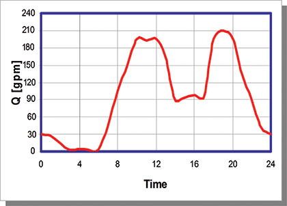
Figure 1
Figure 1 is a typical domestic water consumption flow profile.
The flow profile in figure 1 shows the demand increases in the morning and again in the afternoon to the maximum flow of 190 gallons (719 liters) per minute. Then the flow demand gradually drops off until it stops in the night hours. The peak flow is required for only about three hours of the day. The majority of the time the flow is less than 50 percent of peak flow. A pump system with two pumps would better match the flow profile compared to a single 100 percent pump. Two 50 percent pumps with VFD control ensure that the pump system operates near each pump’s peak efficiency the majority of the time compared to a single pump. One 100 percent pump would run near peak efficiency for less than half of the time. This example shows relatively small flow requirements, but the same variable flow requirements hold true for larger applications, where even more energy can be saved.
VFD-CONTROLLED PUMPS
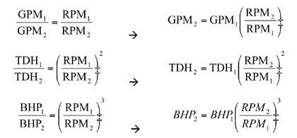
The Affinity Laws state how the performance of a pump changes with changing pump speed (RPM).
The brake horsepower reduces by a factor of the speed cubed, with speed reduction in the pump. That means small reductions in pump speed can have large reductions in brake horsepower.
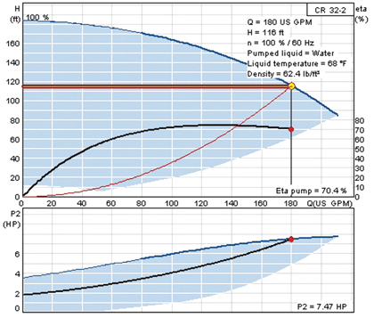
Figure 2
Below is an example of a constant pressure application with two different flow rates that compares a VFD control pump to a fixed speed pump with a pressure-regulating valve (PRV). Figure 2 shows the first condition is 180 gallons (681 liters) per minute at 50 psi boost or 116 feet.
The horizontal line represents the control curve and is the required constant pressure of 116 feet TDH.
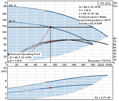
Figure 3
The second operating point is 90 gallons (341 liters) per minute at 116 feet. Figure 3 is the VFD control pump using speed reduction.
The pump’s brake horsepower is 3.77 horsepower and the pump speed is 85 percent using VFD control. The lowered pump speed reduces mechanical noise, providing quieter pump operation.
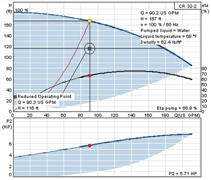
Figure 4
Figure 4 below is a curve for a constant speed pump and a PRV to maintain the required pressure (116 feet).
This pump builds 167 feet of pressure at the required flow rate where only 116 feet is needed and consumes 5.7 BHP. The extra pressure is reduced by the PRV. This leftover energy is not being used, and is bled off as surplus pressure. The PRV wastes energy and requires periodic maintenance that can be eliminated with the use of VFD-controlled pumps. The difference in brake horsepower between the fixed speed pump and VFD-controlled pump is: 5.71 – 3.77 horsepower = 1.94 horsepower.
If the reduced operating point was required for 50 percent of the time and operating seven-days a week; using the cost of energy of $0.10 KWh results in a savings of $750 a year based on an overall motor/VFD efficiency of 85 percent. This illustrates how a pump with relatively low speed reduction (15 percent speed reduction) can save significant energy.
The energy savings through use of VFD-controlled pumps is one benefit for system engineers; other considerations are the ability to eliminate PRVs and their inherent energy losses and maintenance costs. VFD-controlled pumps and pump systems allow for precise control of the discharge pressure and have other advantages including:
- Flexibility to electronically “trim” pump(s) when oversized;
- Soft starting of motors so frequent motor starting (motor cycling) is not an issue;
- Smooth and controlled performance ramp up and down; and
- Stop pumps at zero or low flow. Best way to save money when no flow is to turn the pump(s) off.
A LOOK AHEAD
In next month’s conclusion, we’ll detail some of the recommended guidelines for choosing the right pump for your application, as well as examine how the city of Cottonwood, Arizona, successfully managed their aging water delivery system as their community’s population nearly doubled in size.
ABOUT THE AUTHOR
Brian James P.E., is business development manager and Roger Weldon is service engineer for Grundfos Pumps Corporation. Grundfos is the world’s largest pump manufacturer. For more information, visit www.grundfos.us.
____________________________________________
MODERN PUMPING TODAY, August 2015
Did you enjoy this article?
Subscribe to the FREE Digital Edition of Modern Pumping Today Magazine!