


Secondary wastewater treatment, specifically activated sludge treatment, can be broken down into a series of unit processes, each of which are linked to the process immediately before and after by the hydraulics and the biology of the system. For example, in a typical Modified-Ludzak-Ettinger process (MLE process, figure 1), the basic unit processes would be
- Anoxic treatment for microbiological removal of nitrates (“denitrification”)
- Aerobic treatment for microbiological removal of BOD (Biological Oxygen Demand) and conversion of ammonia to nitrate (“nitrification”)
- Internal mixed liquor recycle to return nitrates to the anoxic zone for denitrification
- Secondary clarification to separate the sludge from the treated wastewater
- Sludge wasting (WAS) for removal of sludge from the system
- Sludge return (RAS) for replenishment of active microbes to the treatment tank.
Additional unit processes might be alkalinity control and carbon addition.
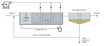
Figure 1: MLE Process Schematic
Process control in a WWTP like this is typically treated as control of the unit processes to meet subordinate objectives. There are a number of reasons for this approach:
- Unit processes are well understood, whereas the linkage between the processes is less understood.
- Nutrient removal plants have become more complex, with lots of moving parts.
- If the control of one unit process fails, that part can be operated manually whereas linked control systems can be more difficult to understand and back up manually.
- The overriding plant objective is to meet permit, and anything that is perceived to jeopardize this is rejected.
- Control systems rely on good, reliable instrumentation, and until recently, this has not been available or economically feasible.
As a result of these conditions, controls are broken down into subsystems:
- Aeration blowers are controlled to a maintain a constant pressure in the air header – as the air demand of the system increases, the pressure drops and the blowers ramp up to maintain the pressure, or vice versa.
- Flow control valves in each aeration zone are controlled by a proportional-integral (PI) control loop that reads and responds to an error signal from the dissolved oxygen (DO) probe – opening or closing the valve to increase or decrease air through the diffusers to maintain the DO set point.
- Blower header pressure and DO set points are static and are manually selected by the operator.
- The internal mixed liquor recycle rate is either constant or a fixed multiple of the influent flow rate.
- Swing zones (zones that can be either aerobic or anoxic by switching diffusers on and off) are switched manually, mostly seasonally.
Manual set points are selected to ensure that the plant meets permit under all expected conditions. However, the level of contamination of the influent wastewater (“loading”) typically varies by a factor of 3 to 8 between daily high and low loading levels. That means that the plant will over-treat during a large part of the day, when the loading is well below the maximum. It also means that the plant consumes more energy than necessary, possibly stresses the biology under low loading conditions, and does not optimally utilize the plant capabilities.
HOLISTIC PLANT CONTROL: PROJECT DESCRIPTION
This paper presents a control system for the city of Lebanon (Pennsylvania) Authority Wastewater Treatment Facility. The plant was upgraded in 2012 to reduce the amount of nitrogen discharged into the Chesapeake Bay Watershed. The nitrogen discharge is measured as a TMDL (Total Maximum Daily Load) of 146,000 pounds (66,224.5 kilograms) per annum, which at the current average daily flow rate of six million gallons (22.7million liters) per day equates to a permissible nitrogen concentration of 8 mg/l.
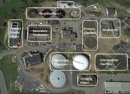
Figure 2: Satellite view of the plant during construction showing major process components
Due to the physical constraints of the plant location (see figure 2), treatment intensity had to be increased without increasing the size of the treatment reactors. For this reason, the plant chose to introduce Integrated Fixed Film Activated Sludge (IFAS) for BOD removal and nitrification, with anoxic/aerobic swing zones. The IFAS elements are shown in figure 3. The IFAS zones have course bubble diffusers to provide the necessary air scouring for the IFAS elements, and the swing zones are outfitted with fine bubble diffusers to provide energy efficient supplemental aeration when needed. The plant has internal mixed liquor recycle for denitrification, and a trickling filter bypass for supplemental carbon when needed for denitrification. The layout of the bioreactors is in figure 4.
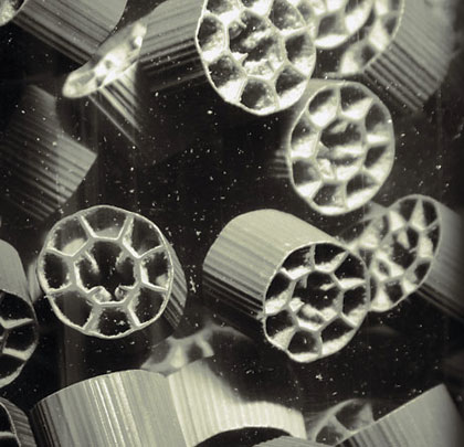
Figure 3: View of the Infilco-METEOR® IFAS elements
The overall control objective is to optimally utilize the plant capacity to meet the effluent permit requirements with the lowest possible energy and chemical consumption and without system disruptions.
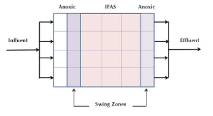
Figure 4: Layout of secondary treatment trains
The control system for the plant has the following functions:
- Determine optimal DO set points in each zone in real time to achieve required treatment levels.
- Maintain DO levels in the IFAS zones.
- Switch on/off swing zones when needed, and maintain DO levels in the swing zones when on.
- Control air flow to each control zone to meet the localized oxygen demand.
- Control blowers to meet the total oxygen demand.
- Minimize system pressure in the air headers (most-open-valve control), particularly when adding/removing fine bubble (swing zone) aeration to coarse bubble (IFAS) aeration.
- Control internal recycle flow to maximize denitrification (total nitrogen removal).
- Control a trickling filter bypass to increase available carbon for denitrification in the anoxic zones.
- Control carbon addition in the tertiary denitrification filter.
The control system could also control the waste rate of the sludge and the solids retention time, if desired by the operator or plant engineer. The basic control system architecture is in figure 5.
EXECUTION
The integration of all of these control objectives was achieved through the combination and integration of two basic control systems: BIOS and BACS.
- The BioChem BIOS: The Bioprocess Intelligent Optimization System (BIOS) uses real time process data to calculate optimal DO set points for each control zone and the ideal internal mixed liquor recycle rate and trickling filter bypass flow rate for minimal energy consumption and maximum total nitrogen removal. It uses a feed-forward control model, the influent ammonium loading data and actual plant operating conditions to calculate optimal nitrification rates and minimum DO set points to achieve the required treatment level. It controls the mixed liquor recycle rate to achieve best possible denitrification for total nitrogen removal. In this particular application it also determines the overall aerobic capacity that is required to meet the demand and switches the swing zones on and off accordingly. The denitrification reaction in the anoxic zone requires BOD in the form of carbon compounds to support the microbial respiration, and in the case of carbon deficiency in the influent flow the BIOS can also control a bypass from the parallel-operating trickling filter treatment train to increase available BOD and maximize total nitrogen removal.
- The BioChem BACS: The Bioprocess Aeration Control System (BACS) uses airflow and residual DO readings to calculate the required airflow to each control zone to meet the DO set point, controls the blowers to deliver the precise amount of air required to meet the demand, and controls the air flow valves to each control zone to distribute the air per system requirements, while always maintaining one valve in a “wide-open” position (typically about 85 percent open) to minimize system pressure and reduce the load (and thus the energy requirements) of the blowers.
The use of swing zones with fine bubble diffusers and IFAS zones with coarse bubble diffusers on the same air header is a peculiarity of Lebanon plant, because the fine bubble diffusers have a significantly higher restriction (and thus higher dynamic pressure) than the coarse bubble diffusers. As a result, the most-open-valve is on one of the swing zones when they are aerated, and on the IFAS zones when the swing zones are not aerated. The swing zones utilize a mechanical mixer to maintain solids suspension when they are un-aerated. This scheme allows the blowers to operate at a pressure of about 7.8 psi when the swing zones are aerated, and a pressure of 6.9 psi when they not. This saves a significant amount of blower energy compared with a constant pressure blower control scheme, where the pressure would always have to be above the level of the fine bubble diffusers, to ensure aerobic operation of the swing zones when they are switched on.
The two control concepts are integrated into one control panel (figure 6) with a single user interface in the form of a touch screen HMI and an Ethernet connection to the plant SCADA. The control panel also houses the entire input/output switching for the field devices and instrumentation. ■
[divider]
ABOUT THE AUTHORS
Tilo Stahl, PhD is a systems engineer at BioChem Technology, Inc., and Frank DiScuillo Jr. is the superintendent of the Lebanon (Pennsylvania) Authority Wastewater Treatment Facility. BioChem Technology specializes in the monitoring, optimization, and control of wastewater treatment processes. For more information, visit www.biochemtech.com.
MODERN PUMPING TODAY, August 2014
Did you enjoy this article?
Subscribe to the FREE Digital Edition of Modern Pumping Today Magazine!