In part 1 of this series, we discussed some of challenges facing pump station owners—specifically the problem of “water hammer” vibration and the resultant maintenance issues that arise due to grease and solids in wastewater than can negatively impact air/vacuum valves. The placement of air/vacuum valves, usually at high elevated points in the pipeline, is especially critical based upon the minimum/maximum flow through the pipeline. This placement will also effect where the transient vacuum events occur in the force main. In order to resolve the important operational and maintenance issues on the force main with air/vacuum valves, the solution to the negative transient pressure wave is best addressed at the pump station itself. Since this was the point of origin for the wave during the pump trip, the solution will be most effective here.
A specification for transient mitigation equipment frequently calls out for a performance guarantee from the respective manufacturer. Whether it is for one day, two days or more of on-site testing and training, the manufacturer is required to “sign off” that the equipment is performing to the level called for in the specification. However without recording transient data at 100 Hz, how does a manufacturer meet its performance guarantee obligations? “Proof of Design” is critical to both understanding the normal operation of the pump station and the reactions of the force main.
As the force main reacts differently due to variations in pressure, flow rate, elevation changes and the presence of entrapped air, the force main system overall becomes increasingly complicated. Entrapped air in particular can produce not only pressure transients but also generate two phase flow with devastating results. Another notable is when pumping downhill which can create a condition whereby the force main may not have enough backpressure to keep the pump running correctly on its curve. Even when variations such as those noted previously are taken into consideration, unsteady flows can still occur as air is being vented from the force main. This is where “Proof of Design” through transient pressure monitoring comes sharply into focus.
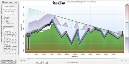
Figure 4 (Above): Surge model animation clearly shows a practical and verifiable solution to negative pressures resulting from a pump trip. In this example, the system’s force main was protected by the use of a bladder surge vessel with results confirmed and documented by a pressure transient monitoring system courtesy of Blacoh Surge Control.
Figure 5 (Featured Image): Example of a Transient Monitoring System that can send immediate notification emails when an abnormal system change has occurred.
Through utilization of a system such as Blacoh’s SurgeWave, with both pressure and flow inputs, the system communicates with the variable speed backpressure control valve and keeps the pump correctly on its curve. As the level of complexity in the force main system increases, a more comprehensive solution could emerge that requires surge vessels to give or receive energy, properly sized and positioned air/vacuum valves, check valves with closing speeds rates matched to the system, control valves and panels to bring it altogether.
An all too common occurrence for operators today is how to address pipeline failures during heavy rainfall when the pump(s) trip due to power failure. This is of particular interest when the system operates normally in low flows without noticeable surge issues. This is just another day in the life of surge mitigation equipment manufacturers who perform start-up/commissioning duties for calibration on a regular basis. However, a “regular basis” must also account for operating conditions that can vary significantly in the field and the effects could take months to be fully identified depending upon the unique aspects of each pump station’s system. A diversity of factors including but certainly not limited to wet well levels, the number of pumps in operation and force main variables are all potential contributors to pump and piping damage. For these reasons, it is recommended that the pump station start-up/commissioning requirements mandate design performance monitoring for a minimum of 30 continuous days of operation.
A brief example of this can be found when the flow rate in the computer surge model shows the steady state flow at 13,195 gallons per minute with a pressure at 72.2 psig with two pumps.
The pump station puts the two pumps into operation and the flow rate seen shows a marked decrease down to 9,375 gallons per minute with the pressure noted at 77 psig. The wet well simply does not have sufficient inflow to meet demand and the pump will turn off on a low level reading giving an operating time of approximately three minutes. When the wet well fills up, the pumps are again restarted but now the flow meter is not recording any flow at all so the pumps turn off in another three minutes. The wet well has been pumped down so why is the flow not seen? Should you be using a mag meter, please insure that it is not partially full. If your system is pumping downhill and only one of the two pumps is in operation, the pipeline may only be partially full.
In order to compare the actual field performance of the system with what the computer surge model projected, the pressure data must be captured and recorded. The rate of capture must be sufficiently high enough to provide sampling data necessary for the computer to present a true image of what is happening. With transient pressure wave speeds in excess of 3000 feet/second, a minimum of 100Hz data recorded is recommended.
For More Information
Frank Knowles Smith III leads the Blacoh Surge Control team as the executive vice president. Smith is a well-respected trailblazer in fluid dynamics with three decades of academic, design, and application experience. The foremost expert on surge control, Smith’s specialties include pump station/pipeline design and computer modeling, piping components, instrumentation, and electrical control panel design. Steve Mungari is the business development manager for Blacoh Surge Control. Mungari has over two decades of process control experience from industry leaders such as Parker Hannifin Corporation and Burkert Fluid Control, which specialize in the field of fluid measurement and control technologies. His background encompasses diverse markets in life science, gas analysis, hygienic processing, and water treatment industries. For more information, visit www.blacoh.com.
____________________________________________
MODERN PUMPING TODAY, September 2016
Did you enjoy this article?
Subscribe to the FREE Digital Edition of Modern Pumping Today Magazine!