Since its introduction as a plant-wide lubrication method in the United States, oil mist lubrication has been extended to over 100,000 process pumps and electric motor drivers. Many articles, books, and conference papers describe application details and the overwhelmingly favorable experience with oil mist (see Bibliography). The overall advantages of oil mist in bearing failure avoidance and maintenance cost reduction are well documented. Oil mist is particularly well known in the hydrocarbon processing industry (HPI) where the American Petroleum Institute (API) and International Standards Organization (ISO) took the lead in recognizing the importance of oil mist. Both API 610 and ISO 13709 Standards for pump design indicate how centrifugal pumps must be designed and manufactured for optimized lubrication by oil mist, should potential users specify or require this type of lubrication.
There are other API recommended practices, such as RP 686 and RP751, which establish the benefits obtained from oil mist technology. These recommended practices (RPs) include equipment maintenance procedures and improvements in mechanical seal reliability. While most applications are focused on process-centrifugal pumps and their drivers, oil mist is also used on small steam turbines, cooling tower gears, forced draft blowers and virtually any machine incorporating rolling element bearings. Most of this equipment operates in North and South America, the Middle East, Australia, and the Pacific Rim countries.
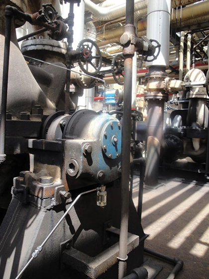
Figure 1: Pure oil mist in centrifugal pump. Note the collecting bottle at bottom of pump bearing housing.
Until recently, however, plant-wide oil mist had not been used in Italy. This prompted an end-user and a major supplier of oil mist technology to discuss their findings. Our collaboration resulted in previously unpublished measurements and investigations conducted jointly by both parties. The article documents the first successful application of oil mist lubrication in an Italian Refinery, where the MTBF (Mean Time Between Failures) of rotating equipment has improved 25 percent during the first thirteen months of system operation.
Using ISO 281/2000 methodology, the co-authors calculated and proved bearing life extentions. These ISO-based bearing life calculations relate the cleanliness level of the lubricant to the bearing life (L10). In addition to the increase in reliability which was thus determined, the co-authors point out enhanced operating safety and energy savings achieved by upgrading the lubrication at this oil refinery.
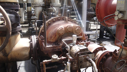
Figure 2: Purge mist applied on steam turbine bearing housing
BACKGROUND
The Raffineria di Milazzo is a joint venture between ENI and Q8; the refinery processes 240 killobarrels per day (kb/d) of crude oil. Located in Sicily’s northeast, it has been designed to accommodate a wide slate of crudes. In recent years, the maintenance department had looked into technology improvements to increase equipment reliability. Rotating equipment reliability is related to optimized lube application and oil cleanliness—two key attributes of oil mist.
However, because this technology is virtually unknown in Italy, Raffineria di Milazzo decided to first study oil mist on critical equipment using a small portable oil mist generator (POMG). A centrifugal pump driven by a steam turbine in the refinery’s No. 3 Topping Unit was selected as the initial pump set for a number of interesting reasons:
- The MTBF of rotating equipment in this unit was one of the lowest in the refinery.
- It was possible to simultaneously observe pure mist (“dry sump”) as a means of bearing lubrication in the centrifugal pump (figure 1), and purge mist (“wet sump”) as a means of excluding air from the steam turbine’s bearing housing (figure 2). The same oil mist unit (POMG) would be used for pump and driver (figure 3).
- Earlier observations and oil analyses had shown the presence of substancial quantities of particles and water in the lubricant. Many distress events and reduced equipment reliability had been traced to lubricant contamination.
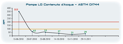
Figure 3 (Feature Photo): Oil mist lubrication demonstration with a small portable oil mist generator. The centrifugal pump is driven by a steam turbine. Free steam explains oil contamination risks.Figure 4 (Above): Water present in oil. Centrifugal pump before/after pure (“dry sump”) oil mist lubrication (with pure oil mist, the analysis was done on coalesced oil collected near the bearing housing drain).
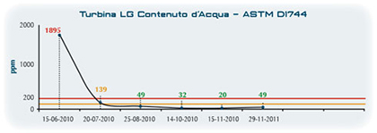
Figure 5: Water present in conventional oil sump. Steam Turbine before/after applying oil mist purge. Purge oil mist is often called “wet sump.”
STARTING THE TEST
The oil mist lubrication testing phase was initiated in June 2010. The portable oil mist generator (POMG) shown in figure 3 was commissioned at that time.
The tests showed very favorable results. Within a few weeks it was possible to measure and observe a significant reduction in oil contamination caused by water and solid particles (figures 4 and 5). Demonstrably improved reliability and equipment life could be expected.
No bearing failures were experienced during six months of intense observation. After operating the demonstration POMG and carrying out exhaustive follow-up on all variables involved, it was decided to move to the next stage. An investment proposal to retrofit oil mist lubrication in the thirty-nine centrifugal pumps and four steam turbines of No. 3 Topping was presented to Refinery Management.
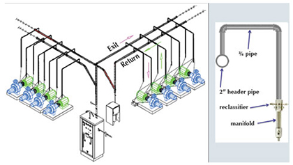
Figure 6: Oil mist system layout. Sloped return headers lead back to the oil recovery units. Coalesced oil mist is collected in small containers at the edges of pump baseplates and manually pumped to the nearest return header
PROJECT EXECUTION DESCRIBED
A survey of the unit was made and shown as a closed oil mist system schematic (figure 6). The feasibility of installing all elements without interfering with normal operation of the unit was confirmed. An IVT oil mist generator (OMG) console (figure 7) and six residual oil mist recovery systems with 656 feet (200 meters) of piping were included in the proposal. Refinery project personnel and the potential vendor ascertained that adequate lubrication would reach every point.
The unit-wide system was commissioned in late November 2011. During the first weeks of equipment operation a notable decrease in bearing operating temperatures was recorded (table 1). Two reasons were given: With conventional liquid oil lubrication, bearing rolling elements plough through the oil and frictional heat is generated. With pure oil mist there is no longer a liquid oil level. The continuous flow of oil mist lubricant at approximately 68 degrees Fahrenheit (20 degrees Celsius) contributes to efficiently dissipate whatever frictional heat still exists. Overall, less frictional heat means higher mechanical efficiency of the equipment—energy savings of typically 1 to 2 percent.
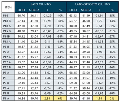
Table 1 represents a summary of temperature decreases recorded in the first month of operation. On average, a decrease of 19 percent was recorded on these seventeen process pumps.
Extensive data collection started from the time the unit-wide oil mist system was commissioned. Throughout the first year of operation every conceivable oil mist system operating variable was logged-in. The primary reliability indicators on pumps and drivers in No. 3 Topping were compiled. Accurate data would allow determining cost and savings and comparing these with anticipated or claimed payback for this investment. Data collection would also help define if extending this technology upgrade to other Refinery Units at Milazzo was justified.
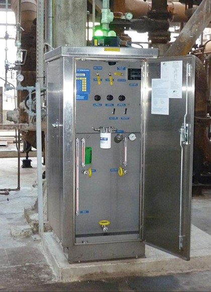
Figure 7: IVT oil mist lubrication console in No. 3 Topping Unit at Raffineria di Milazzo
AVAILABILITY AND RELIABILITY
It is worth noting that all operating variables of the unit-wide oil mist system have remained within the recommended range. These include moisture content (dew point) of the instrument air supply at the oil mist console, oil mist header pressure, oil-air mixing temperatures, mist density, etc. Also, the system has been continuously monitored from the DCS control room. Throughout its now thirteen months of operation the oil mist lubrication system at No. 3 Topping has proved to be 100 percent reliable.
When the technology study was initiated and even before its implementation at Raffineria di Milazzo, questions were raised regarding the use of an oil mist lubrication system without a full spare. Therefore, answers were sought in extensively reviewing prior experience with the now over 2500 large-scale systems in successful operation world-wide. The important findings were listed as follows:
- An oil mist system does not have any moving parts or components prone to wear.
- For flawless operation the system requires only clean instrument air and an oil supply.
- The system does not require electric power to operate. (Note: Electric power is used by instruments that monitor variables).
- Each console at Milazzo contains two mist generators, one a main and the second an auxiliary. Switching over from the main to the auxiliary–if it should ever be needed—would be very easy and could be done in 30 seconds.
- All critical system variables are monitored in real time in both the console and in the DCS control room.
- There are more than 2,500 oil mist lubrication systems operating around the world. Considerable data have been compiled on the effective reliability and availability of these systems. Most modern systems have been in operation for decades with zero downtime.
- Electric motor drivers can easily be added to the oil mist lube system in the future
- Oil mist is the “ultimate filter” because dirt resists being atomized in an oil-air mixing unit
In our second installment, we will examine the technical and economic justifications for converting to oil mist lubrication using mean time between failures.
_______________________________________________________________________
ABOUT THE AUTHOR
Cristian Schmid is a professional engineer with over thirteen years of experience in lubrication engineering in the oil and gas industry. He joined Grupo Sicelub Lubritech in 2000 and has been working in different technical and commercial areas in Argentina, México, and Spain. Davide Nevoso holds a degree in mechanical engineering and has worked as a maintenance engineer at Milazzo Refinery. He is a specialist in rotating machinery, lubrication, and mechanical seals.
_______________________________________________________________________
MODERN PUMPING TODAY, May 2013
Did you enjoy this article?
Subscribe to the FREE Digital Edition of Modern Pumping Today Magazine!