


PART 2/2
In part one of this article, we examined two common systems, one using compressible gasses, and the other using non-compressible liquids, that provide uniform distribution of cooling fluid in both cooling applications and many spray applications. In this month’s concluding installment, we’ll take a closer look at the benefits of the calculations for compressible flow as well as for expansion factor as it relates to the change in the density of an ideal gas. As you will see, accurate measurement and thoughtful calculation can save operators many hours of regret—not to mention a boon to the bottom line.
OLD NEWS IS GOOD NEWS
An old article in a text book from the 1960s provides a good answer—in that, they suggested that with a pipe of constant diameter, the head losses through the nozzle were approximately equal to the friction losses equal to about one-third the frictional flow in the pipe.
Put in scientific terms, the friction head or hf is equal to the value shown in equation 2:
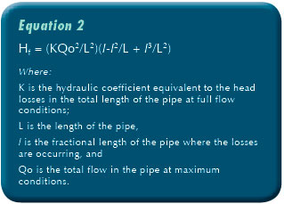
Remember that you will need to have the head greater than the hydraulic head on the outside of the pipe.
Another way to look at the solution to the problem is to perform an analysis across the orifice. In a simple case we have If the value of C is 0.60, and the value of the large pipe flow is Q and the individual orifice value is q, and the hydraulic head differential between the inside of the pipe and immediately outside the pipe is hd which accounts for the submergence of the pipe. If you set the nozzle losses greater than the pressure head against the pipe plus the pipe friction, the design works.
An example will help. I have a 3-inch (76.2 millimeter) pipe 300 feet (91.44 meters) long. I want to distribute 100 gallons (378.54 liters) per minute through it uniformly. Head losses through the length of the pipe are 4.47 feet of head loss per 100 feet. The pipe is submerged by 3 feet of water. The total head loss is then 4.47 * 3+3 = 16.41 feet of head or just about 5 PSIG.
I want to use 30 nozzles or orifices, and each one should take about 3.33 gallons per minute.
The nozzle size should be
![]()
In the proper units q = 7.42*10-3 cubic feet per second, g is 32.18 square feet per second and h is 16.41 feet. Running the numbers that gives A2 is 5.381*10^-4 square feet or 0.0775 square inches.
That translates to a hole of approximately 0.0987 inches in diameter or a 3/32 inch hole. The water will flow out uniformly. The water will also flow in uniformly, under vacuum conditions. If the system is going to be a free draining system with no vacuum in the pipe, then the available head with be that on the outside of the pipe less the friction losses in the pipe, meaning that a larger opening will be required.
[alert alert_type=”error” ] Warning: If you are trying to use this design for developing a uniform draining system, remember that the maximum vacuum you can reliably have on the system, is about negative 13 psig or about 30 feet of suction. Beyond that you will start to get cavitation in your pump.[/alert]
COMPRESSIBLE FLOW
Compressible flow occurs in air and other gases. The formula must account for a few more variables such as the initial and final states and temperatures. As the air crosses the orifice it changes temperature, decreasing sharply as it expands from the nozzle. In order to prevent the moisture in the gas from freezing and possibly plugging the nozzle, one needs to account for the change in temperature across the orifice.
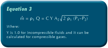
The equations for compressible gas flow across a nozzle are a bit different.
For this we need to introduce an entire new set of terms:
Equation 2 above needs to be modified by introducing the expansion factor to account for the compressibility of gases.
[h2]CALCULATION OF EXPANSION FACTOR[/h2]
The expansion factor Y, which allows for the change in the density of an ideal gas as it expands isentropically (no net change of energy through the nozzle or orifice), is given by:
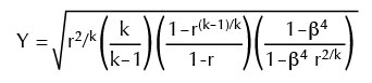
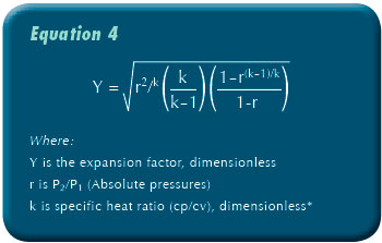
For values of β (ratio of orifice diameters) less than 0.25 β4 approaches 0 and the last bracketed term in the above equation approaches 1. Thus, for the large majority of orifice plate installations:
NOTE: For air, it is 1.4, which is good enough for most cases, unless one really has a heavy vapor concentration in the gas. Or get Cv and Cp from online tools and references such as those found on EngineeringToolbox.com.
Substituting equation 4 into the mass flow rate equation (equation 3), and making a few substitutions using the Gas Law, we get:
And make sure all the units are consistent, if using English units, then the temperature is in Rankine degrees. And thus, the final equation for the non-choked (i.e., sub-sonic) flow of ideal gases through an orifice for values of β less than 0.25.
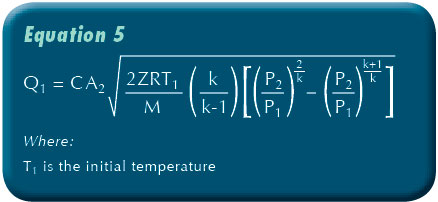
Where:
k is specific heat ratio ( ), dimensionless
m is mass flow rate at any section, kg/s
Q1 is upstream real gas flow rate, m³/s
C is orifice flow coefficient, dimensionless
A2 is cross-sectional area of the orifice hole, m²
P1 is upstream gas pressure, Pa with dimensions of kg/(m•s²)
P2 is downstream pressure, Pa with dimensions of kg/(m•s²)
M is the gas molecular mass, kg/mol (also known as the molecular weight)
R is the Universal Gas Law Constant is 8.3145 J/(mol•K)
T1 is absolute upstream gas temperature, K
Z is the gas compressibility factor at P1 and T1 and dimensionless—but most of the time it is 1 for air at environmental temperatures generally encountered.
A final check of the velocity of the gas through the orifice should be made to insure that it is not supersonic (exceeding the speed of sound) and it should be checked for temperature to insure that the gas vapor which contains water will remain above freezing. This is important for both vacuum extraction and vapor venting.
The entire program can be easily arranged on an Excel spreadsheet, and the total orifice size and pressure drop and gas flow can be easily calculated. Then using the same essential data, select a drill size and a spacing which is suitable to the length of the horizontal well. A brief calculation of the total orifice size and appropriate area is very straight forward and easily performed.
■ ■ ■
[divider]
ABOUT THE AUTHOR
David L. Russell, P.E., is a chemical and environmental engineer and the founder of Global Environmental Operations, Inc., a specialty environmental consulting firm serving clients all over the world. Mr. Russell is an in-demand consultant for projects ranging from environmental process designs and hazardous wastes to water systems and wastewater treatment. He can be reached at 770.923.4408 or by visiting www.globalenvironmental.biz.
MODERN PUMPING TODAY, May 2014
Did you enjoy this article?
Subscribe to the FREE Digital Edition of Modern Pumping Today Magazine!