


PART 1/2
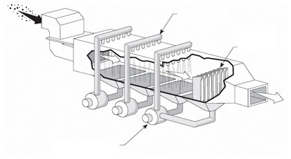
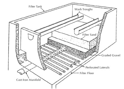
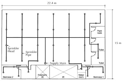
Cooling applications and many spray applications require uniform distribution of the cooling fluid over the affected area. Examples include, spray lines, spray towers, certain types of air pollution control spray systems, filter backwash systems, fire sprinkler systems, and other types of cooling lines where the cooling fluid is a gas rather than a liquid (see figures 1, 2, and 3).
In all these applications, the conventional analysis can be time consuming and involve many repetitive steps. In the environmental field, there is also the challenge of making sure that a collection or distribution trench has uniform flow over the entire length of the trench. Again, the analysis can be difficult, repetitive, and time consuming. However, some help is at hand.
TWO SYSTEMS: COMPRESSIBLE GASSES AND NON-COMPRESSIBLE LIQUIDS
There are two types of systems, one using compressible gasses, and the other using non-compressible liquids. The analytical approach to both is similar, but the gas system requires additional analysis for compressibility of the gas. Far too often we have seen systems where the pressure close to the distribution header is quite adequate, but as the flow approaches the end of the lateral line from the header, the pressure is low, and as a result, the flow is low, sometimes much less than the design figure. It is this unequal distribution which can cause unequal cooling or cleaning in a production line or spray system.
Here are some simple design tips that will allow development of effective collection and distribution systems wells for both liquids and gasses. One note of warning though, if you are designing a sprinkler system for fire protection be sure to have your design reviewed and designed by the sprinkler company and the fire marshal. Defer to their wishes because it is their system.
WATER AND NON-COMPRESSIBLE FLUIDS
The same technique can be used for the headers and the laterals coming off of them. The application is straightforward: How does one get uniform distribution along the length of the pipe even if there is liquids being pumped from the pipe or drawn into the pipe? The distribution system needs to be tailored to the piping system. The key is the head loss through the pipe.
ORIFICES AND PIPE LOSSES
The formula for energy losses through a nozzle or orifice plate is the same, just the coefficient of discharge is different. That formula is shown in Equation 1:
All of it has to be in the same appropriate units. The coefficient of discharge is between 0.59 and 0.61 for most orifice plates, depending upon Reynolds Number for the fluid system. Others have reported slightly higher loss coefficients, between 0.60 and 0.66. The higher coefficients were determined experimentally on piping systems which had four openings around the pipe (see M. Duchene and E. McBean’s write-up in the American Water Resources Association’s Water Resources Bulletin, Vol 28, No 3, June 1992).
The challenge in the design is to get the losses and the flow through the orifice holes equal to the flow in the pipe. This can require a bit of ingenuity in the design process. The ideal situation is to design the distribution system so that the flow and the losses at the end of the pipe are zero.
Without going into a lot of discrete math, one way of designing the system would be to analyze the pipe at each perforation. The flow at one location is Q, just before some nozzle or junction that takes away a finite amount of flow (q) for a new value of for the flow (Q-q) after the junction. From hydraulics, that means that if the pipe size is the same, there is a new velocity [V-vq= (Q-q)/Ap], where Ap is the inside area of the pipe, and the new velocity is (V-vq). This means that the next set of friction losses in the pipe must be evaluated for a very short distance until the next opening or perforation.
If there are n perforations, the computation would require n+1 different frictional calculations for head loss and friction in the length of the perforate pipe, and might require a number of different piping sizes, decreasing to the end of the pipe. That’s just unrealistic and extremely cumbersome.
[h2]A LOOK AHEAD[/h2]
Next month, in part 2 of this analysis, we’ll continue to examine these calculations and their benefits, plus look closer at formulas for compressible flow as well as for the calculation of expansion factor as it relates to the change in the density of an ideal gas. ■
■ ■ ■
[divider]
ABOUT THE AUTHOR
David L. Russell, P.E., is a chemical and environmental engineer and the founder of Global Environmental Operations, Inc., a specialty environmental consulting firm serving clients all over the world. Mr. Russell is an in-demand consultant for projects ranging from environmental process designs and hazardous wastes to water systems and wastewater treatment. He can be reached at 770.923.4408 or by visiting www.globalenvironmental.biz.
MODERN PUMPING TODAY, May 2014
Did you enjoy this article?
Subscribe to the FREE Digital Edition of Modern Pumping Today Magazine!