


Positive displacement flow meters have long been the technology of choice for applications requiring very precise delivery of high-value liquid product. Recently, mass flow meters (also called Coriolis Flow Meters for the French scientist, Gustave Coriolis, who pioneered the technology in the 1830s) have increased their presence in the marketplace. These meters have been successfully utilized in a wide range of both rotodynamic and positive displacement pump systems. While rotodynamic pumps generate relatively smooth flow, positive displacement pumps such as piston pumps, gear pumps and sliding vane pumps generate pressure pulses during operation. Since mass flow meters utilize vibrations to measure fluid flow we questioned how well they would work with equipment that generates pressure pulses during operation. This study focuses on flow measurement in positive displacement pump systems that utilize rotary sliding vane pumps as the means of flow generation. Further, we narrowed our scope of interest to relatively thin liquids. The transfer and change of custody of high-value liquids (fuels) is the primary focus of the study. We tested the meters on 30-SSU solvent and LPG (liquefied petroleum gas) to simulate one of the most common applications of our sliding vane pumps. Higher viscosity liquids were not considered and are outside the scope of this investigation.
THEORY OF OPERATION
Coriolis mass flow meters do not measure flow directly in terms of gallons per minute or cubic meters per hour (m3/hr). Instead, fluid density and the Coriolis forces (mass flow) are measured, which are then used to calculate flow rates.
There are typically two measuring tubes in a Coriolis meter, which are formed into a slightly bent tube or a more dramatic “U” shape. The measuring tubes through which the fluid flows are constantly expected to oscillate at their resonance frequency. The resonance frequency is the frequency at which the measuring tubes are “most willing” to oscillate. Any change in the density of the fluid produces a corresponding change in the resonance frequency of the entire vibrating system (measuring tube and fluid). The resonance frequency, therefore, is a function of fluid density—the higher the density, the lower the resonance frequency. The resonance frequency is then compared to the empty-tube resonance frequency, allowing the mass of the fluid in the tubes to be calculated. Since the volume of the tubes is known, the density of the fluid can be calculated.
Typically, the two tubes in the meter are vibrated 180 degrees out of phase with each other. As flow (mass) passes through the meter, the phase angle between the tubes changes. The phase-angle change of the tubes is caused by the Coriolis Effect and is proportional to the mass flow rate of the fluid in the tubes. Using the mass flow rate and dividing by the density provides a volume flow rate. Both the density and the mass flow rate are measured directly and are therefore independent of the temperature, pressure, viscosity, conductivity and flow profile of the fluid passing through the meter. This means that, in theory, a Coriolis mass flow meter can be used to measure any type of fluid flow. The meter output can be corrected to a standard reference temperature if desired.
There are several significant advantages to using Coriolis mass flow meters:
- Because the flow passes through smooth tubes with no moving parts, there is no mechanical wear of the measuring elements. There are also no parts subject to abrasion, erosion or corrosion.
- Particulates nearly as large as the measuring tube diameter can pass through the meter without issue. Typically, the measuring tubes have a diameter one-half that of the meter’s piping connections for a two-tube meter and are approximately equal to the piping connections for a single-tube meter.
- Coriolis meters are not affected by temperature or pressure. They measure mass flow directly, which does not change even if the temperature or pressure of the fluid changes. Therefore, no pressure or temperature compensation is required.
Accuracy is typically listed as 0.1 to 0.2 percent of the flow rate being measured. This is much more accurate than mechanical meters, which are listed as being within 0.5 percent of full-scale flow. Because other types of meters also need to have pressure and temperature compensation, additional error in these measurements can increase the overall flow error to as much as 3 percent. - Because of their very precise accuracy, the Coriolis flow meters have a turndown ratio of about 100:1 or more. This means that if a meter is rated for a maximum flow rate of 200 gallons (757 liters) per minute, it is still accurate down to 2 gallons (7.57 liters) per minute. Typical mechanical meters have a turndown ratio of 10:1. An orifice plate’s turndown ratio is more like 5:1.
- There is minimal pressure drop through a Coriolis mass flow meter with lower-viscosity fluids. The only pressure losses are caused by the splitting of the flow into the two measuring tubes. Orifice plates, flow nozzles, venture tubes and positive displacement meters can have significant pressure losses associated with the meter.
- Coriolis meters are unaffected by changes in viscosity during a process or batch run. Orifice plates and the other pressure-differential meters need to be calibrated for various viscosities and the viscosity needs to be measured during operation to ensure accurate metering.
Admittedly, there are also a few disadvantages to using Coriolis mass flow meters that must be considered: - Pressure drop through a Coriolis meter may increase significantly with increasing viscosity when compared to other technologies such as ultrasonic or magnetic flow meters. The pressure drop is caused by the split of flow into two or more smaller pipes that are not straight. The smaller bent pipes can increase pressure drop when compared to the straight-through flow of ultrasonic or magnetic flow meters.
- Typically, a mass flow meter has a higher initial cost than that of other technologies for similar applications.
- Depending on the amount of “bend” in the measuring tubes, the space required to locate a Coriolis flow meter can become significant. However, this is offset by a reduction in the amount of straight pipe (flow straightening) usually required on the inlet and discharge sides of many types of flow meters.
MASS FLOW METER EXPERIENCE
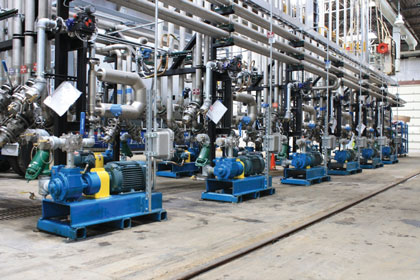
To understand how Coriolis mass flow meters might interact with Blackmer® sliding vane pumps, two flow meters were purchased. The first meter, from Endress+Hauser, was a 3 inch (76.2 millimeter) Model 83F. This meter was used for performance testing of various pumps on 30-SSU through 2,000-SSU fluids. The second meter, an Emerson™ Micro Motion 2 inch (50.8 millimeter) Model CMF200, was installed on Blackmer’s propane test loop. Meters were evaluated for setup and installation, pressure pulses and flow precision.
SETUP AND INSTALLATION
The Endress+Hauser meter was installed on a mobile cart. A 3 inch (76.2 millimeter) 100-mesh strainer was installed on the inlet side. The piping looped around on the cart with an elbow directly on the inlet side of the meter. This was done because, per the recommendations of both manufacturers, no straight-line inlet piping is required on the inlet or the outlet side of the meter for straightening. Manufacturer recommendations were to install the meter vertically to allow easier removal of air when the meter is started empty. However, the meter was deliberately installed horizontally to investigate the effects of improper meter mounting orientation. Typical usage for this meter was to test a pump with a specified fluid and viscosity, drain the pump and piping system, and then set it up with another pump with a specified fluid. The Endress+Hauser meter has a flow capability of 800 gallons (3028 liters) per minute of water.
The Emerson meter was also installed in the LPG test loop horizontally. However, in keeping with LPG custody transfer protocol, a vapor eliminator and back-check valve were installed with the meter. This system is also used in a similar manner: a pump is tested, piping is drained and the pump is removed for the next pump installation. The Emerson meter has a flow capability of nearly 400 gpm of water.
The following observations and lessons were learned from using the meters:
- Both meters have pressure-pulse dampening software available. Both meters had this feature deactivated; testing indicated that it was not necessary.
- Flow readings were unexpectedly smooth on both meters, much less than with any PD meters that were used previously. Fluctuation of the Emerson meter on LPG was observed to be ±0.1 gallons per minute for flows to 40 gallons (151.42 liters) per minute. The Endress+Hauser meter fluctuation was similar, with fluctuations up to perhaps ±0.3 gallons (1.14 liters) per minute on flows up to 300 gallons (1136 liters) per minute, and greater.
- The Coriolis mass flow meters are acoustically much quieter than PD meters. This was especially noticeable with the meter on the LPG system. Because there are no moving parts there is no vibration generated to resonate with associated piping. However, when the meters are powered and not filled with liquid, they do emit a high-pitched hum. The humming can be eliminated by keeping the meters filled with liquid or by de-energizing the meters.
- The LPG meter, with the vapor-elimination system, experienced no difficulties reading flow when started empty. Since the back-pressure and vapor-elimination valves eliminated vapor quite well, the meter filled with liquid as quickly as the PD meter used earlier.
- There was difficulty getting rid of air from within the Endress+Hauser meter, which had been intentionally mounted horizontally on the mobile cart. Both manufacturers recommended the meters be installed vertically and the recommendation was proven correct. Above flow rates of 100 gallons (378.54 liters) per minute, air was successfully removed in a very short time (less than one minute). At lower flow rates (less than about 75 gallons [284 liters] per minute), a valve was used to throttle the outlet of the meter to increase pressure in the meter. This allowed the trapped air to dissolve in the test fluid and flush out of the meter after several minutes. Below about 30 gallons (113.56 liters) per minute it was not possible to completely get rid of the air.
- Air in the meter creates turbulence and reduces the accuracy of the density measurement. Air in the meter also causes the density measurement to become unstable, which could be observed on the meter register. When functioning properly, density fluctuation was typically ±.0005 SG or less – the fluctuation was out to the fourth decimal point, or in the ten-thousandths range. When air was in the system the SG varied approximately ±.05, or two orders of magnitude greater than without air.
- The Endress+Hauser meter was re-orientated vertically to test the air-elimination process. At a flow rate of less than 3 gallons per minute, (on an 800 gallons [3028 liters] per minute meter) after about five minutes of operation, it was possible to flush the air out of the meter without using a throttling valve on the outlet side of the meter. With more flow rate, or by throttling the outlet of the meter, air removal was accomplished in less time.
PRESSURE PULSES
A point of concern when utilizing Coriolis mass flow meters with positive displacement pumps is that PD pumps generate pressure and flow pulses that a Coriolis meter might respond to. PD pumps move fluid by filling a fixed-volume chamber and then forcing the fluid out of that chamber. The PD pump could have as few as one chamber, such as a single-piston pump, or twenty or more, as in a gear pump. The pressure pulses are generated by each individual pumping chamber being filled and emptied, and the frequency of the pulses is a function of the number of chambers in the pump and the speed at which the pump is operated. Coriolis mass flow meters measure vibration of the tubes and frequency variation of the tubes in order to measure flow. We wanted to understand if the vibrations generated by Blackmer sliding vane pumps would interfere with the flow-meter measurements.
Distortion of flow-meter vibration measurements would, in theory, tend to be maximized near the frequency at which the flow meters operate. From discussion with the mass flow meter manufacturers, the resonant vibration of the mass flow meters is approximately 200 Hz. To evaluate possible interference of pressure pulses with flow measurement, several sliding vane pumps were tested at a nominal 100 psi with varying shaft speeds to create a range of vane frequencies from 80 Hz to 260 Hz. High-speed pressure and flow data was collected and minimum and maximum pressures and flows were recorded. The results indicated that there was no correlation between the vane frequency, pressure pulsing and measured flow at the meter.
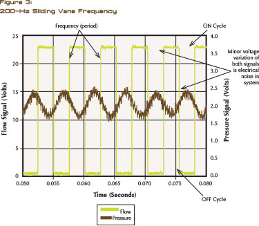
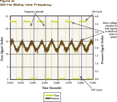
Another attempt was made to look for possible interference between the pump and the flow meter. A pump was operated at sliding vane frequencies of 120 Hz and 200 Hz (figure 2 and figure 3) for comparison, with pressure on the pump outlet and in the flow meter held at a nominal 100 psig. The flow and pressure signals from the flow meter and the pressure transducer were monitored with a digital-signal processing oscilloscope.
The Coriolis flow meter used for the test provided a frequency output signal, producing a 50 percent on/off square-wave function between 0.5 VDC and 22.5 VDC. The number of on/off cycles produced by the meter per unit of time is proportional to the flow passing through the meter. While operating at the conditions outlined above, the signal from the flow meter was inspected for distortions of voltage values, shape of the output function and the timing of each signal step over time. Other than minor pressure and flow fluctuation that were within the expected values of the system, no significant output-wave from distortions were found. Figure 2 and figure 3 show samples of the results.
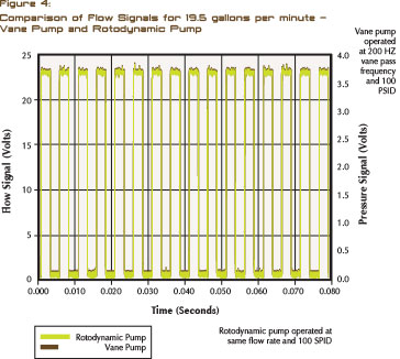
The final investigation pursued was to operate a sliding vane pump with the vane-pass frequency the same as the Coriolis mass flow meter’s resonant frequency and record that output wave form from the meter and then compare it to the same conditions with non-pulsed flow from a rotodynamic flow source. The vane pump was operated at a sliding vane pass frequency of 200 Hz to maximize the opportunity for meter resonance. The flow rates and operating conditions for both pumps were held equal at 19.5 gallons (73.82 liters) per minute and 100 psig on 30-SSU solvent. The results (figure 4) show that the wave forms are identical. The meter handled both types of flow (pulsed and non-pulsed) with equal precision.
A LOOK AHEAD
In next month’s concluding article, we will examine the test result across different flow rates as well as observations from the field. As the analysis will show, the goal of greatly improved measurement accuracy and very good reliability in a production environment can be achieved and documented. ■
About The Author
Jeff Sietsema is the Research & Development Lab Manager, and Richard E. Foster is Director of Engineering for Blackmer®, the leading global brand of innovative and high-quality rotary vane and centrifugal pump, and reciprocating compressor technologies for the transfer of liquids and gasses. Part of PSG®, a Dover Company, Blackmer pumps and compressors are used in a multitude of applications in the Process, Energy, and Military and Marine markets. For more information, visit www.blackmer.com.
MODERN PUMPING TODAY, January 2015
Did you enjoy this article?
Subscribe to the FREE Digital Edition of Modern Pumping Today Magazine!