Although fulfilling the original design intent and functioning as intended, many “traditional” sealing systems found in industrial applications waste considerable amounts of energy.
The uncontrolled injection of seal flush liquids—usually associated with Plan 32 piping described earlier in Part 2—promotes such waste. In contrast, controlled injection uses a control valve (similar to figure 1); this partially alleviates waste and may save two-thirds of the “uncontrolled” fluid flush flow previously used with Plan 32. However, whatever fluid co-mingles with the pumpage in the pump casing (the “hydraulic end”) will still require costly, energy-consuming, downstream separation, evaporation, and/or re-heating. Part 3 now explains the workings of fluid control valves as they reduce injection rates to one-third of “uncontrolled.” But first an overview of how mechanical seals function and why clean flush is always needed for long-term satisfactory seal performance.
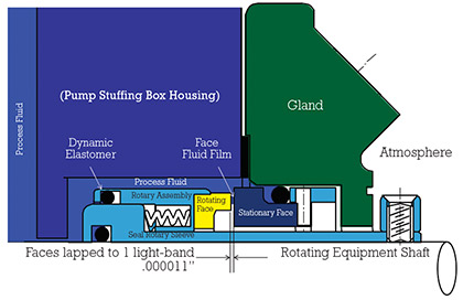
Featured Image: Figure 2: Sealing points—How a mechanical seal work.
Above: Figure 2: Sealing points—How a mechanical seal works
MECHANICAL SEALS AND FLUSH FLUID CONTROL
Ideally, a seal should last as long as the equipment on which it is installed. Yet, the mechanical seal is often the first component to fail. As we explore why seals often fail first, we note that seal faces operate on a fluid film very similar to the fluid film that is needed for a bearing to function. We can appreciate bearing lubrication; we periodically change the oil in our automobiles when the engine lubricant appears to lose one or more of its desirable properties. Bearings will not last if the lubrication oil is contaminated with water or foreign particulates. Likewise, we should not expect seal faces to give satisfactory long-term operation in thick and dirty fluid films, or in slurries.
This is why we have an incentive to do something different to seal applications with high solids content. We should consider upgrading the seal environment in liquor processing and similar applications. We become familiar with how a seal works and examine the remedy for fixing challenging or reliability-limiting applications.
The rotary and stationary faces in figure 2 are lapped surfaces that are essentially perfectly flat. The fluid film between these two surfaces creates the seal between the rotation of the shaft and the stationary housing of the rotating equipment. If this fluid film is not controlled consistently, the faces will leak and the seal will enter into a failure mode.
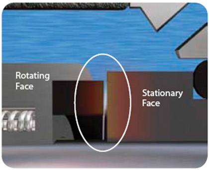
Figure 3: Mechanical seal faces with a fluid film of fresh, clean water will run cooler and longer.
TECHNICAL ISSUES: FLUID FILM CONTROL
It is possible to seal pumps with slurry-resistant single mechanical seals. However, we protect the fluid film in bearings and must do the same in mechanical seals. Just as in bearings, seal surfaces (“faces”) operate on a thin fluid film. If this film is unstable or not clean, the seal will fail.
If a single seal is used, the film between the faces is the process fluid (see figure 3). If the pump runs dry, the seal runs dry; the seal then generates heat and the film may vaporize (see figure 4). All of these conditions can lead to premature failure and seal fluid film instability is the leading cause of failure.
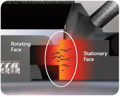
Figure 4: Dry-running of mechanical seal faces destroys the fluid film, resulting in overheating and failure.
Fluid film instability must be controlled in both single and dual mechanical seals. Single seals use API Plan 32 to flush away contaminants. Dual seals use a secondary fluid between the inner and outer seal face sets. The manner in which the secondary fluid is controlled and pressurized determines the long-term fluid film stability in a dual mechanical seal. Fluid film stability can be achieved and controlled when the barrier fluid pressure is greater than the seal chamber pressure as shown in the following illustrations.
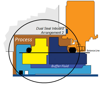
Figure 5: API-682 Arrangement 2
In figure 5 the caption refers to “API-682 Arrangement 2” seals, whereby the process (depicted here as a slurry) is at a higher pressure than the buffer fluid. The slurry is forced by the differential pressure across the seal faces forming the fluid film; observe the brown slurry between the seal faces in this figure 5. This is not ideal; eventually the slurry will abrade the seal faces to the extent where the faces will no longer retain sufficient face flatness to maintain an effective seal.
Figure 6 refers to an “API-682 Arrangement 3,” which is the preferred method for setting up a dual mechanical seal in process liquor applications. The barrier fluid is at a higher pressure and it is forced across the seal faces. If we now closely observe the film between the rotary face (in yellow) and the stationary face (dark blue), we will see the clean blue color barrier fluid.
If the seal face fluid film can be stabilized to ensure long-term reliability, the next technical point to address is how to manage the quality and the pressure of the barrier fluid system.
Reliability efforts should center on how to control the barrier fluid pressure and the general quality of the barrier fluid. Controlling the fluid film is a primary purpose of the piping plans and control systems. Well-designed piping plans and associated fluid controls maintain the barrier fluid is always at a higher pressure; the support system must be designed and operated so as to remove the heat generated by the seal faces.
CONTROLLING SEAL WATER INJECTION
Seal water injection can be controlled using flow restriction devices. These devices are made for single and dual seal applications. The traditional way to reduce water injection is to use a seal water control and monitoring system. Manufacturers and their respective brands include:
- AESSEAL – FlowTrue® (see figure 1)
- EagleBurgmann – FLC200
- Flowserve – Seal Gard™
- ESKO – Flowmeter ESF / EDF
- John Crane – Safematic® Safeunit™
A.W. Chesterton Company and John Crane promote a variant to the traditional flow control device.
The Chesterton product is marketed as the T-30 Intelliflow™ Water Saver; the John Crane Company offers its SmartFlow® Intelligent Seal Water Control System. These two products are designed to work with dual seals in a water-to-drain set-up (see figure 6 in Part 1 from this series in the October 2015 issue of MPT). The literature for the T-30 Intelliflow™ describes a calibrated thermal valve which continuously senses the temperature of the barrier fluid. The valve opens when the barrier fluid temperature exceeds the preset temperature. Upon opening the valve releases hot fluid which cools the seal. John Crane’s literature describes a similar concept. The system incorporates a heat-activated shape memory alloy spring which functions by mechanically opening and closing the flow channel. The system automatically accommodates new operating conditions, i.e., variations in pressure and temperature (For more details, visit A.W. Chesteron online at www.chesterton.com or John Crane at www.johncrane.com). Both product descriptions and installation references contain cautionary statements about the quality of the barrier fluid water. The SmartFlow® literature refers to the water quality standard incorporated in John Crane’s Safematic Division’s SAFECLEAN Seal water Filter System, which recommends “no particles larger than 50 micrometers” as well as other recommendations for impurities, iron, and hardness.
In general, the various manufacturers of the injection control devices bulleted above defined these as compact devices which can be expected to reduce seal water consumption by about one third while keeping packing and mechanical seal performance in their respective optimal ranges. All consider water quality as an important parameter not to be overlooked when using Plan 32 as a seal flush arrangement or as a dual seal barrier fluid flow control.
Recall, please, that retaining Plan 32 will require cooling and cleaning the sealing area in order to enhance reliability, but flow-controlled seal water injection is designed only to reduce the flow to minimum levels. The life expectancy and overall cost effectiveness of these flow control products could be reduced if they are retrofitted to a sub-standard water source. Moreover, in its seal energy audit, a competent vendor will again emphasize that reduced flow from any of the above flow meters in Plan 32 must be selected in the context of seal chamber dimensions. The internal pump clearances and fits must take into account an internal restriction bushing to maintain 15 feet per second flow velocity.
Otherwise, the flow reduction could impact reliability.
The special combined flow and heat control devices manufactured by Chesterton and John Crane are designed to control flow through a dual seal relative to changes in heat generation. These devices keep unneeded (and therefore wasted) flow in balance with the increased flow required for cooling. The cautionary statements for water quality suggest that the benefit will be optimum when the seal water is filtered. Single seal flushes inject water directly into the process and an uncontrolled dual seal injects water as the inner seal face set wears. Dual seal water injection is often un-detected until the process is shut-down and the seal water fills process tanks. In sharp contrast, that is not the case with self-contained water management system with in-service monitoring. These will be explained next.
CONSIDER SELF-CONTAINED WATER MANAGEMENT SYSTEMS
Today’s advanced self-contained water management systems are superior to other approaches from lifecycle cost points-of-view. They should be considered when designing a sealing system. Self-contained means that virtually zero flush fluid enters the pumpage. These units or systems are cost-effective and environmentally ideal. Most important: They represent mature technology in every sense of the word.
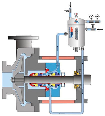
Figure 7: Plan 53-A
SEAL SUPPORT SYSTEMS AND PIPING PLANS
A Water Management System combines two API Piping Plans: Plan 53-A and Plan 54. However, for at least the past two decades, totally self-contained sealing systems have been available. These advanced combined-plan systems can supplant energy-wasting flush plans which, although inexpensive when first commissioned, result in cooling and diluting the process. Where the downside to a stand-alone Plan 53A is the need to replenish the seal water during periods of process upset, combining fluid film control with the traditional Plan 53A has moved to the forefront of proven “green” technology with cost-effective long-term reliable results.
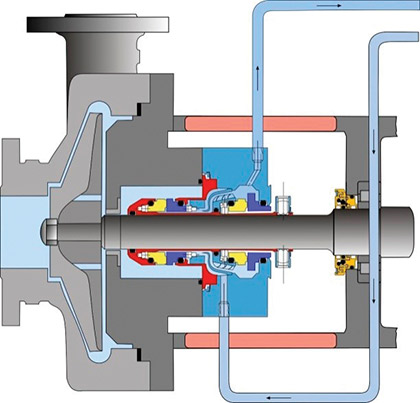
Figure 8: Plan 54
In a Water Management System the fluid film is controlled. Virtually no barrier (flush) fluid is injected into the process. As in Plan 53-A (see figure 7), the Water Management Tank is mounted well above the seal application. The system pressure is controlled by a regulator on the top of the tank. Unlike traditional Plan 53-A systems, water is connected directly to the tank from a water header, which is similar to Plan 54 (see figure 8).
If there is a loss of barrier fluid, the water source from the Plan 54 connection automatically recharges the system. A flow indicator on top of the tank indicates water is entering the Water Management System, as seen in figure 9.
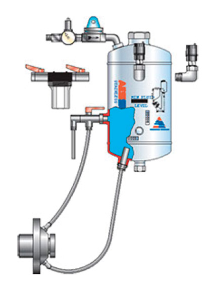
Figure 9: Water management system
Water quality is controlled by using an in-line filter prior to the regulator. The filter can be replaced on-line. Replacement is infrequent because the filter does not see continuous flow of water, which makes it possible to improve filtration from 50-microns down to an optimal 1-micron.
The Water Management System removes the requirement to have the operator manually check and fill the tank because it is self-filling. Continuous pressurization of the barrier fluid ensures the fluid film is always a clean and cool liquid.
Variables to consider include seal size, pump speed, process pressure, barrier pressure, ambient temperature and process temperature. A heat generation program provided by the system supplier guides and stipulates the correct sizing and features needed to fully specifying a Water Management System. The program will confirm the level of heat removal from the system.
The energy savings calculation is based on zero flow and no reheat or evaporation cost because a Water Management System eliminates the need to inject seal water into the process.
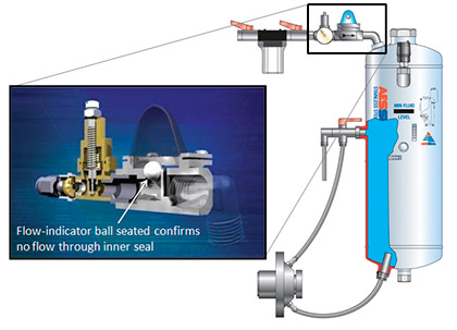
Figure 10: Self-contained water management system incorporating relevant means of monitoring
TECHNOLOGY UPGRADE AND BENCHMARK
Where possible, industry benchmarks are provided from the client site and/or from industry data. The data represent a Mechanical Seal Energy Audit benchmark comparison of the recommended upgrades.
This section of an audit would therefore take into account data provided from client experience to verify which technology provides both energy savings and reliability improvement. Needless to say, it is unwise to invest in energy saving technology that adversely impacts the reliability of the equipment.
The technology should provide means of condition monitoring that would indicate when the rotating equipment experiences inner seal leakage into the process. The technology would also provide the P-F (Point-to-Failure) interval where the operational performance of the equipment should be more closely monitored to prevent unscheduled maintenance events.
The previous discussion on Plan 32 flush cleanliness needs for mechanical packing and single mechanical seals would be re-visited at this point in a seal energy audit report, as would the fluid film control for dual seals.
Features are provided in a Water Management System for condition monitoring and for the control of the fluid film at the inner seal face set. During in-service inspection, the water flow indicator is a visual in-service way to detect if there is any water being consumed and injected through the inner seal face.
It is not uncommon that, prior to the installation of a Water Management System, it was not possible to detect the amount of dilution on Plan 54 water to drain installations. The starting point is to assume there is 100 percent dilution and use percentage estimates to calculate the operating cost, in this case the operating cost savings.
About The Author
Tom Grove is an executive vice president at AESSEAL Inc., one of the world’s leading specialists in the design and manufacture of mechanical seals and support systems. He can be reached at tom.grove@aesseal.com. Heinz P. Bloch, P.E., is one of the world’s most recognized experts in machine reliability and is a Life Fellow of the ASME, in addition to having maintained his registration as a Professional Engineer in both New Jersey and Texas for several straight decades. As a consultant, Mr. Bloch is world-renowned and value-adding. He can be contacted at heinzpbloch@gmail.com.
____________________________________________
MODERN PUMPING TODAY, December 2015
Did you enjoy this article?
Subscribe to the FREE Digital Edition of Modern Pumping Today Magazine!