In one of the three previous parts this series of articles has dealt with the cost to reheat and/or evaporate flush injection from API Plan 32. It has also addressed industry technology that can be deployed to make seal flush piping plans more energy efficient while at the same time improving the reliability of the sealing device in the rotating equipment. Improvements and savings accrue from the application of best practice alternatives to API Piping Plans 32 and 54. The use of a modified API Plan 53A in the form of a Water Management System was described in Part 3; it eliminates the need to reheat and evaporate diluents. Available benchmark data prove the reliability benefits of this approach.
PUMPS USED IN CONDENSATE SERVICES
In the last of this series of articles, Part 4 now addresses the pumps used in condensate services. During many surveys the auditor will note pumps that are leaking hot condensate—a condition very often found in the paper industry. We can make good use of an authoritative source, the U.S. Department of Energy’s Steam Tip #8 by quoting from it in this Mechanical Seal Energy Audit:
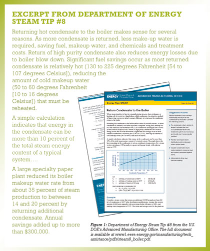
The bulletin in figure 1 gives a working example with calculations for determining the annual water, sewage, and chemical savings plus the annual fuel savings. In this particular field energy audit, the total annual savings due to return of additional 10,000 pounds per hour of condensate equaled $121,760.
Taking a conservative approach, the calculations in the last section assume a leak-rate of 3 gallons per minute to equal 1,500 pounds of steam per hour.

WHY DOES A CONDENSATE PUMP PERSISTENTLY LEAK?
Using separator pumps as a case in point, these pumps are taking condensate off the condensate receiver tank after the paper machine rolls. It is not customary for the receiver level controls to be manually overridden. Overrides can occur when the machine is brought on-line and steam must be kept in the rolls to prevent these from flooding. As steam enters the separator pump, the mechanical seal face set cannot seal steam. The lapped faces will become distorted and severe leakage will result.
Condensate pumps traditionally use API Plan 02, API Plan 11, API Plan 21, or API Plan 23. These plans use a single mechanical seal with one of these plan options.
Plan 02 means the seal chamber has no pipe connections. How and why would Plan 11, 21, or 23 be used?
The graphic on the next page shows hypothetically where each plan operates on a vapor-temperature curve for condensate. In order to understand how the traditional plans have been used, assume the condensate pump has a suction pressure of about 30 psig and the condensate is 200 degrees Fahrenheit (93 degrees Celsius). The discharge is 80 psig and there is naturally no change to the discharge temperature. For discussion purposes, the seal generates heat; assume the resulting temperature increase is 25 degrees Fahrenheit (-4 degrees Celsius). What is the pressure in the seal chamber? The seal chamber pressure depends on the pump design. Vanes on the back of the impeller or balancing holes near the eye of the impeller are used in design to control the axial thrust on the pump shaft. These pressure balancing techniques mean the pressure in the seal chamber will be closer to suction pressure. Again, it depends on the pump and seal manufacturers usually recommend consultation with the pump manufacturer to verify this pressure.
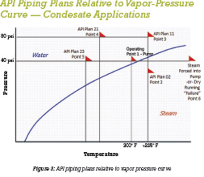
Figure 3 shows theoretically where the operating points are on the vapor-temperature curve.
Operating Point #1
Seal chamber pressure and temperature: Pressure is just above the vapor point and the pump is pumping a liquid (water/condensate). The temperature and pressure in the seal chamber are such that the seal chamber contents are still in the liquid state.
Operating Point #2
API Plan 02. Depending on the actual pressure in the seal chamber, the seal faces generate heat and a pressure drop occurs across the seal face from 40 psig to 0 psig. Therefore, the fluid film between the seal faces could be vaporizing (“flashing”) as temperature increases and pressure drops.
Operating Point #3
API Plan 11 has been selected for this service. This plan increases the seal chamber pressure to 80 psig, assumes no cooling for seal face generated heat. The safety margin comes from higher pressure.
Operating Point #4
API Plan 21. A heat exchanger has been added to the discharge bypass line and the pressure is raised while the product is cooled. The safety margin comes from higher pressure and cooling of the condensate.
Operating Point #5
API Plan 23. The seal chamber is isolated and product is circulated through a heat exchanger. The mechanical seal circulates the liquid with a pumping ring (a “flow inducer”). This plan is more energy efficient than Plan 21 because the cooler only removes the heat generated primarily by the seal. There is also a small amount of heat soak from the process that passes an internal isolation restriction bushing in the seal chamber.
Operating Point #6
Failure: At any point during the life of the rotating equipment, if the pump sees steam because of operational upsets or the condensate receiver level causes the pump to run dry, the mechanical seal fails and the condensate pump leaks. This is the core issue to address.
DUAL SEAL SOLUTION
The solution recommended is to use a dual seal with a secondary fluid consisting of treated clean condensate. The purpose of the secondary fluid is to cool the seal faces during normal operation and to serve as a lubricating fluid when the pump runs dry or steam is forced through the pump. This deals with the core failure issue of dry running or steam being forced through the pump.
By using a dual seal arrangement to mitigate the dry-running conditions caused by operational upsets affecting the condensate receiver, the user should expect years of leak-free service and energy efficiency benefits outlined in the Department of Energy Steam Tip #8.
About the Author
Tom Grove is an executive vice president at AESSEAL Inc., one of the world’s leading specialists in the design and manufacture of mechanical seals and support systems. He can be reached at tom.grove@aesseal.com. Heinz P. Bloch, P.E., is one of the world’s most recognized experts in machine reliability and is a Life Fellow of the ASME, in addition to having maintained his registration as a Professional Engineer in both New Jersey and Texas for several straight decades. As a consultant, Mr. Bloch is world-renowned and value-adding. He can be contacted at heinzpbloch@gmail.com.
____________________________________________
MODERN PUMPING TODAY, January 2016
Did you enjoy this article?
Subscribe to the FREE Digital Edition of Modern Pumping Today Magazine!