


Pumps can be found mounted in many different ways; there are times and places to do things at least cost, and times and places to do it with uncompromisingly high quality. Over the course of the next three installments, this article will familiarize the pump users with the important aspects of base plate installation and some of the preferred options available.
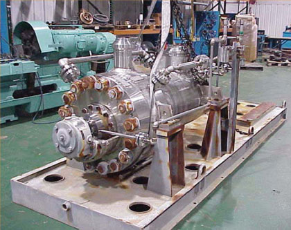
Before considering the most prevalent pump base plate installation options, we need to know more about how pump sets are typically shipped to the purchaser or installation site. In general, process pump manufacturers are asked to provide pumps as a “set” or assembled package comprising pump, driver and base plate (see figure 1).
After ascertaining correct shaft separation to accommodate the selected coupling, and pre-aligning the two shaft centerlines within perhaps 0.020 inches (0. 5 millimeters), pump manufacturers (whom we assume to be our base plate providers) spot-transfer mounting holes from pump and driver to the base plate mounting pads. The pump and base plate provider then proceeds to drill and tap bolt holes that have a diameter of about 0.060 inches (1.5 millimeters) less than the mounting holes (“through-holes”) in pump and driver. Mounting bolts are inserted at this stage of the pump assembly and the complete pump set is now considered ready for shipment as a pre-aligned “mounted” package to the designated recipient.
Receiving the conveniently mounted-for-shipping package has, over the past few decades, led to the erroneous assumption that the entire package can simply be hoisted up and placed on a foundation. However, doing so is not best practice; in fact, how pumps are shipped has relatively little to do with how they should best be installed in the field (see reference 1). The old OEM field service person knew about this issue, but wise old field service folks are no longer employed at the OEM and the ones in charge today just want things done fast. Users are not blameless in the matter. They often allow work to proceed without either specification or procedure. Some users award contracts to the lowest bidder and then “hope for the best.”
ENSURING LEVEL MOUNTING
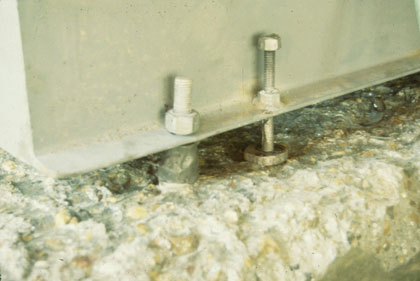
We need to observe that best practices companies (BPCs) will not install the equipment as a mounted “set.” To ensure level mounting throughout, pump and driver are removed from the base plate. The base plate is now placed on a foundation into which hold-down bolts or anchor bolts (see figure 2) were encased when the re-enforced concrete foundation was being poured (see reference 2). Leveling screws are then used in conjunction with laser-optical tools or a machinist’s precision level to bring the base plate mounting pads to flat and parallel condition. Flatness and parallelism are measured side-to-side, end-to-end and diagonally. BPCs require a readily achievable accuracy of 0.001 inches per feet (~0.08 millimeters per meter).
The nuts engaging the anchor bolts are secured next and the hollow spaces within the base plate as well as the space between base plate and foundation filled with epoxy grout.
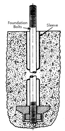
For proper stretch and long life, these anchor bolts (see figure 2) must have a diameter-to-length ratio somewhere between 1:10 and 1:12. The anchor bolts are provided with sleeves or other flexible fill. The sleeves prevent entry of grout and accommodate the differing amounts of thermal growth of a concrete foundation relative to that of a steel base plate.
After the epoxy grout has cured, pump and driver are placed on the base plate and aligned to criteria that conform with best practices—essentially the workmanship guidelines and reliability-focused practices of modern plants (see references 1 and 2). The driver is being aligned to the pump by adding or removing shims from under the driver; dial indicators monitor an occasional soft-foot condition at the driver’s feet. When the pump is bolted down, soft foot and pipe stress are observed on dial indicators. As the pipe flanges are bolted up to the pump nozzles, sensitivity to piping being flanged up is closely monitored. Any dial indicator movement in excess of 0.002 inches (0.05 millimeters) will require making corrections to the piping and using force to pull piping into place is never allowed if the resulting dial indicator movement exceeds 0.002 inches (0.05 millimeters). In essence, process pumps should never be allowed to become pipe supports.
STILT MOUNTING
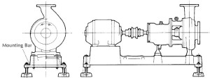
Plants which use stilt mounting (figure 3) often fall short of achieving best-possible equipment reliability. Best practices plants secure their pumps more solidly on more traditional foundations. Stilt-mounted pump sets lack overall stiffness but have been used for small ANSI pumps where the sideways-move capability of the entire installation was thought to equalize piping-induced forces. Among the few advantages of stilt-mounting are low initial cost and ease of floor cleaning in food processing facilities where hygiene is very important.
However, there are serious shortcomings since stilt-mounting will not allow pump vibration to be transmitted through the base plate to the foundation and into the subsoil. Proper foundation mounting permits transmission of vibration which can result in a significant increase in mean time between failures (MTBF), longer life of mechanical seals and bearings, and favorably low total life cycle cost (see reference 3). ■
REFERENCES
1. Bloch, H.P., and A. R Budris. Pump User’s Handbook: Life Extension, 4th Edition (2013). Fairmont Press (ISBN 0-88173-720-8).
2. Bloch, H. P., and F. K. Geitner. Major Process Equipment Maintenance and Repair, 2nd Edition. Gulf Publishing Company (ISBN 0-88415-663-X).
3. Bloch, H. P. Pump Wisdom: Problem Solving for Operators and Specialists (2011). John Wiley & Sons (ISBN 978-1-118-04123-9).
■ ■ ■
[divider]
ABOUT THE AUTHOR
Heinz P. Bloch, P.E., is one of the world’s most recognized experts in machine reliability and has served as a founding member of the board of the Texas A&M University’s International Pump Users’ Symposium. He is a Life Fellow of the ASME, in addition to having maintained his registration as a Professional Engineer in both New Jersey and Texas for several straight decades. As a consultant, Mr. Bloch is world-renowned and value-adding. He can be contacted at heinzpbloch@gmail.com.
MODERN PUMPING TODAY, May 2014
Did you enjoy this article?
Subscribe to the FREE Digital Edition of Modern Pumping Today Magazine!