

In the first part of this article, a major pump OEMs had invited Mechanical Solutions, Inc. to resolve an occurrence of multiple pump driveshaft failures for one of their most important customers, a well-established international ore mining company. They noted objectionable vibration levels accompanying the new pump systems at the mining company’s raw water pumping station in East Africa and that two of the three large pump systems had sustained catastrophic failures. In this month’s conclusion, we will present how analysis of the data presented MSI with the solution and the practical resolution to prevent the damaging combined mechanical stress condition from recurring in any of the three pumping system driveshafts.
ANALYSIS OF THE DATA UNLOCKED THE SOLUTION TO THE PUZZLE
After a timely yet comprehensive evaluation of the test data was completed, it became evident that the inferior tuning of the diesel prime movers had resulted in very strong ½x rpm torsional harmonics throughout each pump system’s drivetrain. The axial and torsional modes of the driveshafts were in resonance with the unusually high 1½x running speed harmonic, which made this response particularly harsh. In fact, the peak torsional oscillations exceeded 90 percent of the mean torque value in each of the driveshafts. The strain gauge data that was recorded during the typical operation of the pump systems showed that the driveshafts also bound up in the axial direction due to inadequate clearance to accommodate thermal growth, which caused the driveshafts to develop large cyclical axial compression stresses in addition to the cyclical stresses from the torsional oscillations. Further, the ODS animations of the test data showed a periodic cantilever bending motion of the right angle gear heads at this harmonic, which moved the horizontal driveshafts axially in the direction of the prime movers.
The design of the welded hollow driveshaft therefore was examined in detail. It was found that, should the weld not have penetrated completely through the wall thickness to reach the inside diameter, the weld geometry would resemble that of a circumferential crack around the driveshaft. A significant stress concentration at the edge of the weld would have been created in this scenario. Thus the finite element analysis (FEA) of the driveshaft that was performed included the weld bead (see figure 7).
The simultaneous alternating torque and axial loading of the driveshaft that had been observed was modeled, and the stress linearization of a path through the thickness of the weld was performed. The combined peak membrane and bending stress that was located near the “crack” in the FEA model was calculated, from which a potential stress intensity factor of 11 ksi (in)½ was predicted. For carbon steels, exceeding a critical stress intensity factor of about 10 ksi (in)½ indicates that, were a crack or material flaw present, it would likely propagate under an alternating load. Hence the FEA predicted a “borderline” but still significant probability of failure from the fatigue loading of the weld bead. The stress intensity level in the welded driveshaft coupling attachments, due to the combined oscillating loads and steady stress, was great enough that fatigue fracture of the welded joints would be expected to occur.
Based on the coordinated inspection, testing, and analysis of the pump systems which was performed, it became evident that a jammed coupling spline, which was caused by an insufficient axial gap in the driveline, led to the excessive oscillating axial and torsion loads. The two types of oscillating loads had combined to create an unanticipated cyclical load condition, which was severe enough to have precipitated the weld failures in two of the three pump system driveshafts.
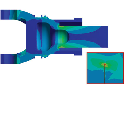
Figure 7: The figure shows a color contour plot of the von Mises stress distribution in the pump system driveshaft, which was predicted through finite element analysis. Geometry which resembles a crack around the circumference of the shaft would have been created, should the weld not have penetrated through the wall thickness of the hollow driveshaft completely to the inner diameter, as was predicted to be the case based on failed part inspections and reported weld procedures. As is depicted in the enlarged view within the figure, this geometry would have caused a substantial stress concentration at the edge of the weld, which would have led to crack initiation if alternating loads (as determined to exist by test) were present during the shaft’s operation.
THE MACHINERY PROBLEM HAD A PRACTICAL RESOLUTION
To prevent the damaging combined mechanical stress condition from recurring in any of the three pumping system driveshafts, the installation of torsionally and laterally flexible couplings between the prime movers and the right angle gear pinion shafts was recommended. Commonly used elements of machinery trains, the flexible couplings would introduce much needed elasticity in the longitudinal direction of each driveline, and they also would attenuate the responses to any torsional oscillations in the drivelines that might be sourced in an imperfectly tuned diesel engine. Since only one or two of the three pump systems in the station operated at any given time, coupling replacement could be implemented gradually without completely removing the station from service, thereby enabling the mining company to avoid additional, costly downtime.
For added assurance, it was suggested that the diesel prime movers should be tuned properly at the earliest opportunity. In their then-present state the prime movers had generated the unusually high torque impulses at ½x rpm multiples which set up the detrimental load condition within the pump system drivelines. This action was recommended to be a part of the facility’s equipment maintenance program.
Within the span of one week, coordinated testing and analysis had been applied successfully to identify the root cause of the puzzling driveshaft failures at the pumping station. The decision makers were provided well-defined evidence, along with practical, effective recommendations to solve the machinery problem. This project clearly demonstrated that Operating Deflection Shapes (ODS) and Experimental Modal Analysis (EMA), when coupled with appropriate analytical techniques and sound engineering evaluation, formed a powerful troubleshooting tool both to comprehend perplexing machinery issues, and to facilitate effective solutions for the complex vibration problems which can occur in pumping systems. ◆
Maki Onari is manager of turbomachinery testing and Juan Gamarra is senior staff engineer at Mechanical Solutions, Inc. (MSI). MSI performs consulting and R&D, as well as provides design, analysis and testing services for organizations throughout the US and overseas. MSI is proud of its outstanding track record in solving some of the world’s most difficult technical problems. For more information, call 518.320.8552 or visit www.mechsol.com.
____________________________________________
MODERN PUMPING TODAY, July 2015
Did you enjoy this article?
Subscribe to the FREE Digital Edition of Modern Pumping Today Magazine!
![]()
Curing a Raw Water Pumping Facility’s Unremitting Driveshaft Failures Part 2 of 2
