

Baldor-Dodge Raptor’s easy to assemble, patent-pending split rubber element significantly decreases total cost of ownership and extends driven equipment life. Designed for drop-in interchangeability, the Raptor offers easy installation and reduced maintenance in an innovative design. When it is time to inspect or maintenance the coupling, it is important to know what to look for so elements can be replaced when appropriate and unplanned downtime is minimized.
Inspection of Raptor elements can be performed statically or dynamically. Static inspection involves stopping and locking/tagging out all equipment. With the coupling guard removed, the Raptor element is then visually inspected. A strobe light can also be used to inspect the coupling while it is still in operation. The strobe light is adjusted until the frequency matches the running speed of the equipment. This method allows the operator to inspect the coupling without stopping the equipment. It is important to exercise extreme care when inspecting couplings using the dynamic inspection method. This method should only be used if the operator can access the coupling through a screen or hatch in the coupling guard and can perform the inspection safely. If the coupling cannot be accessed safely, the static inspection method should always be used.
STANDARD CREEP PATTERNS
The Raptor’s natural rubber elements are designed with a 50 percent lower torsional and bending stiffness. Lower torsional and bending stiffness reduces bearing loads, lowers vibration, and dampens shock loading. Raptor elements that have run for two years may begin to see minor levels of element creep at the element split. Creep is defined as the progressive wind-up of an elastomer. Wind-up is the amount of angular displacement achieved when torque is applied to a coupling. This creep is normal and is a result of the low torsional and bending stiffness of the natural rubber element. Figure 1 depicts Raptor elements with standard creep patterns. These elements are still well within their useful life and do not need to be replaced at this time.
Over time foundations settle, vibration occurs, and some level of misalignment typically occurs. When elastomeric couplings are misaligned, energy is created in the form of heat, in a phenomena known as hysteresis. As long as this heat is dissipated properly, the elastomeric couplings can handle high levels of misalignment. However, if misalignment is severe and exceeds acceptable limits, then the combined effect can result in poor performance and premature failure. The same is true as a result from high application torque and vibration.
CONCERNS WITH MISALIGNMENT, TORQUE, OR VIBRATION
Initial signs of this break down from excessive misalignment, high application torque, or excessive vibration can be seen in the form of tearing or deterioration of the Raptor’s natural rubber element at the split between the two element halves. Figures 2 and 3 depict different forms of tearing or deterioration at the element split. If any of these wear patterns are seen on your Raptor element, plans should be made to replace it at the next scheduled down time. If the tearing is severe, the element should be replaced at the time of the inspection.
Every application presents its own challenges for elastomeric couplings. High levels of vibration, torque spikes, excessive misalignment, and other similar events can decrease the life of your Raptor’s natural rubber element. During the inspection of the element, it is good practice to look for tearing or separation of the Raptor element’s wings. Figure 4 shows examples of the type of tearing you may experience. If tearing or separation of the wings is detected on your Raptor element, plans should be made to replace it at the next scheduled down time. If the tearing is severe, the element should be replaced at the time of the inspection.
KEYS TO INSPECTION
If tearing at the element split, tearing of the element wings, or separation of the wings is found during element inspection, steps should be taken to determine the cause of failure in the system. Alignment of the connected equipment should be checked and corrected to minimize the effects of misalignment on the system. System requirements should also be checked and compared with the Raptor performance ratings to ensure that the proper size and service factor has been selected. Any sources of excessive vibration should also be isolated to maximize coupling life.
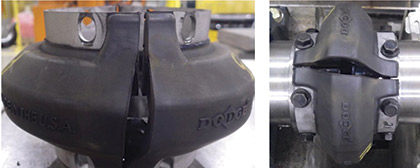
Figure 1: Baldor-Dodge Raptor standard creep patterns.
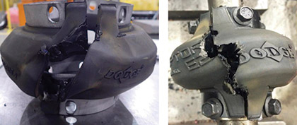
Figure 2: Typical tearing patterns at the element split as a result of excessive misalignment, torque, or vibration.
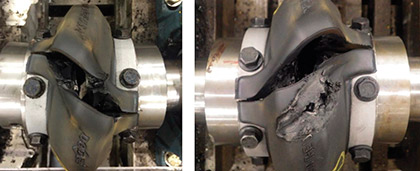
Figure 3: Typical tearing patterns at the element split as a result of excessive misalignment, torque, or vibration.
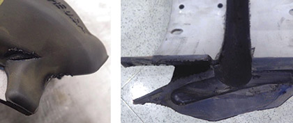
Figure 4: Typical tearing patterns at the element split as a result of excessive misalignment, torque, or vibration.
About the Author:
Alex Vitou is development engineer for couplings and power transmission products.
Baldor Electric Company, a member of the ABB Group, markets, designs, and manufactures industrial electric motors, mechanical power transmission products, drives, and generator sets. For more information, visit www.baldor.com.
____________________________________________
MODERN PUMPING TODAY, May 2016
Did you enjoy this article?
Subscribe to the FREE Digital Edition of Modern Pumping Today Magazine!
![]()
Element Inspection Criteria for Couplings
