In part 1 of this article, we introduced a case study wherein two new process pumps at an oil refinery were experiencing bearing issues. Now in the fourth day of addressing the problem—which has led to multiple diagnoses and the fabrication of a new bolt-on bearing housing end plate for one of the pumps—the operators were facing down basic engineering questions related to design and factory fabrication issues.
DESIGN DISCREPANCIES FROM THE MANUFACTURER
There were engineering design discrepancies, initially acknowledged by the pump manufacturer, in regards to the following: First, the constant level lubricators were not located at the bearing housing elevation needed to maintain an oil level at the center of the sight glass. The as-installed constant level lubricators maintained an oil level well above the top of the sight glass. The original diameter oil rings would therefore run much deeper into the oil reservoir.
Also, the pump manufacturer’s general arrangement drawing showed both oilers at the 3 o’clock location. The inboard bearing housings had the constant level lubricator at 9 o’clock—they can’t both be right (see references 1 and 2).
Furthermore, the sight glass nozzles are visibly sloped downward such that the center of the sight glass was below the desired oil level, disregarding the constant level lubricator elevation issue.
The factory test ran the 3,600 rpm design pumps at 1,800 rpm with the oil level at half the sight glass level, and without the constant level lubricators being filled. A filled constant level lubricator would have resulted in a much higher operating oil level during the factory testing.
The refinery requested from the pump manufacturer dimensional information on how to resolve the oil level issue:
- Bearing housing drawings to evaluate the bottom of the oil ring relative to the operating oil level.
- Sight glass nozzle elevation on the bearing housing.
- Constant level lubricator nozzle elevation on the bearing housing, taking into account the internal oil level set point of the constant level lubricator itself.
- A water cooled bearing housing is really not useful on pumps with rolling element bearings. Moreover, pumps with a water jacket have limitations on where the sight glass and oiler nozzles can be located without penetrating the water jacket. The refinery believed that bearing housing fabrication drawings are required to assess this issue.
- Proper oil ring dimension for operating at 3,600 rpm with ISO VG 68 oil and with an assumed 3/8 to 1/4 inch oil ring depth in the oil reservoir. Most oil rings are not designed for thick oils and deep immersion.
- The originally used inboard bearing for this pump model was a roller bearing. The P-45C/D pumps both have roller bearings as inboard bearings, but the housings do not have the required components to firmly fix the position of the outer race. The refinery had requested contacts or names of other same-model-users that have the inboard roller bearings; the refinery wanted to know how the bearing was assembled on pumps owned and successfully operated by others.
The refinery requested contacts for other users of the same model pump to investigate possible successful modifications that have been used to resolve similar design issues.
The manual indicted coverage for different model pumps. What changes are involved for this particular model pump?
The refinery acknowledged that both pump owner and pump manufacturer had been treating failure symptoms instead of the root causes of unsatisfactory bearing and lubrication performance. They well recognized that there was no assurance that the steps taken were the correct engineering fixes for long term reliability. The user’s and manufacturer’s interim measures were based on general pump practices, but without any engineering validation by the pump manufacturer. And, of course, it was not the function of their field service people to re-engineer a product. It should, however, be the manufacturer’s responsibility to submit rigorous factory engineered solutions. People—including designers—can make mistakes, but lack of response can become a big problem for user and manufacturer. So, choose your pump manufacturer carefully. Better yet, avoid problems altogether.
Feature Image –Figure 2: Modern closed-loop oil mist module for use on important process pumps, fans, blowers, etc. The unit replaces troublesome constant level lubricators and unreliable oil rings (Photo courtesy of Colfax Industries, Houston, Texas).
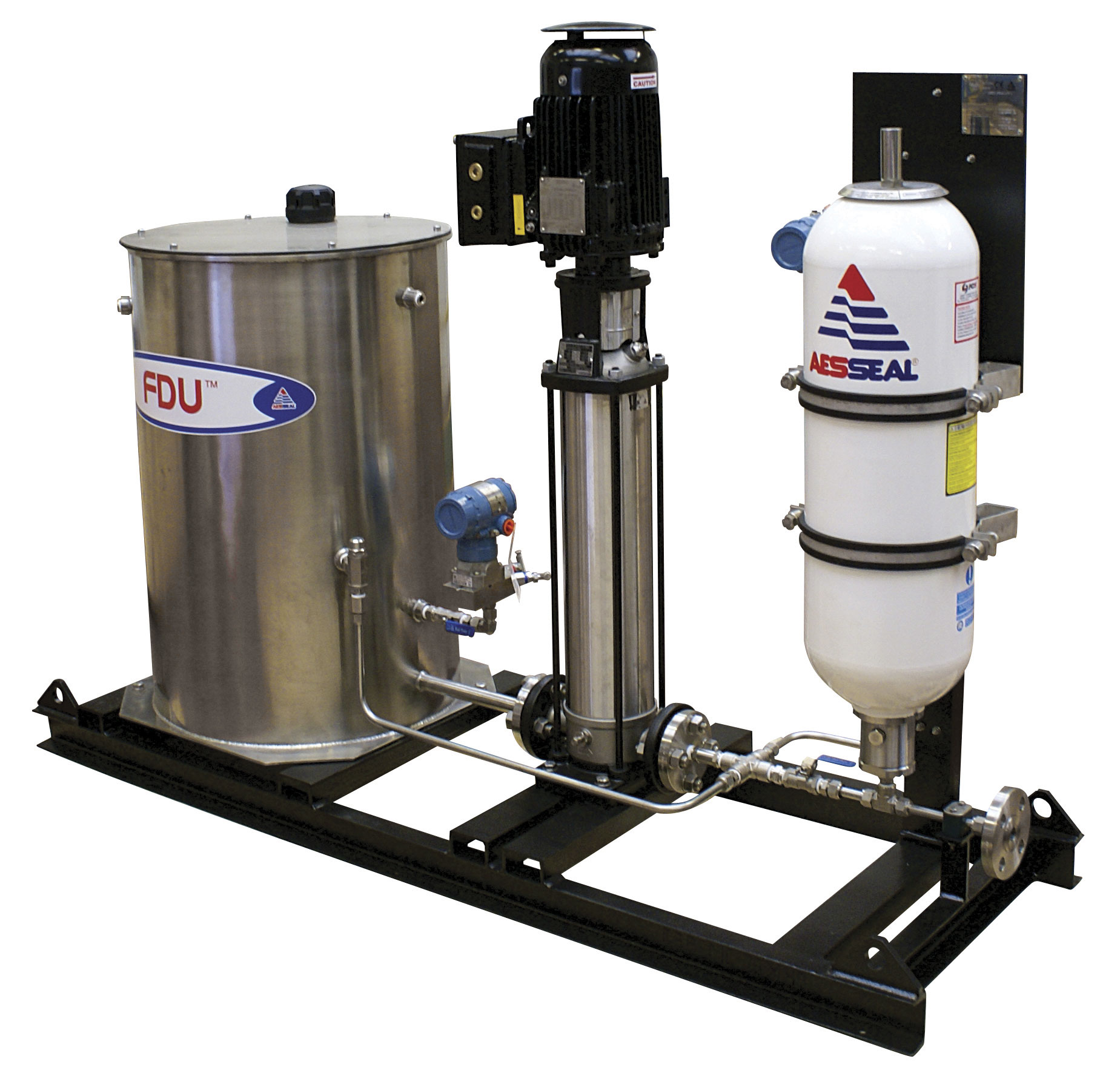
Above: Figure 3: Although originally designed for dual mechanical seals, this pressurized pump-around system is easily adapted to provide continuous and reliable oil spray lubrication for process pump bearings (Courtesy of AESSEAL Inc., Rotherham, UK, and Rockford, Tennessee, USA).
AVOIDING THE PROBLEM
When, after ten days, there still was no response from the manufacturer’s engineering department, the refinery activated more responsive and productive sources. As a refinery engineer put it: “On-the-fly best guesses and field-generated modifications are not the way to solve pump problems which so obviously have far-reaching safety and reliability impact.”
In this instance, there was such potential impact. It has been suggested that the two pumps were designed and produced with skimpy bearing housings. Their oil sump volumes could have been out of harmony with assured long-term reliability. For a certainty there are potential safety and reliability hazards whenever oil rings are either not properly designed or improperly fabricated. The oil rings in this instance were not suitable for depth of immersion and viscosity grade of the lubricant.
With the help and concurrence of competent consultants, the refinery took steps to entirely discard oil rings and constant level lubricators on these pumps. They now use a pre-packaged oil mist module (see figure 2) to provide lubrication to both pumps.
A well-designed oil mist module (see figure 2) will incorporate a heater and helpful supervisory instrumentation. For process plants preferring circulating (liquid) lube oil, another option presents itself. Small pump-around units originally designed for dual mechanical seal barrier fluids (including oil) and similar to the one shown in figure 3 are readily available as upgrades. They can be fitted and connected by pump users who place safety and reliability ahead of the lower initial cost of oil ring and old-style static sump lubrication.
REFERENCES
- Bloch, Heinz P.; “Pump Wisdom—Problem Solving for Operators and Specialists” (2011), John Wiley & Sons, Hoboken, New Jersey
- Bloch, Heinz P. and Allan R. Budris, “Pump User’s Handbook: Life Extension,” 4th Ed., (2013), Fairmont Publishing Company, Lilburn, Georgia.
ABOUT THE AUTHOR
Heinz P. Bloch, P.E., is one of the world’s most recognized experts in machine reliability and has served as a founding member of the board of the Texas A&M University’s International Pump Users’ Symposium. He is a Life Fellow of the ASME, in addition to having maintained his registration as a Professional Engineer in both New Jersey and Texas for several straight decades. As a consultant, Mr. Bloch is world-renowned and value-adding. He can be contacted at heinzpbloch@gmail.com.
____________________________________________
MODERN PUMPING TODAY, September 2015
Did you enjoy this article?
Subscribe to the FREE Digital Edition of Modern Pumping Today Magazine!