


Fouling and cleaning profiles of four types of filter membranes were obtained using Micro-90® and/or Micro® A07. Simulated fouling processes were performed by using either a synthetic oil emulsion or a combination of the synthetic oil emulsion and a calcium acetate salt bridge mixture. Excellent recovery of permeate flux was obtained with the lowest to be 96 percent. The results prove that Micro-90 and Micro A07 are effective at cleaning these types of membranes.
In all four trials, some delamination of the membranes occurred around their perimeters, probably due to the seeding of the membranes in the filtration unit.
Some flux variation occurred during the trials because the optimal pressure of each membrane was controlled manually. This can be seen in instances where the flux rate exceeds 100 percent.
INTRODUCTION
Simulated cleaning profiles are valued by potential customers as providing assurance that candidate cleaners will perform as anticipated in their filtration processes.
Laboratory-based performance data, along with technical support and sufficient samples for on-site cleaning trials, ensure a quick and successful transition to a more effective cleaning regimen.
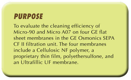
In this project, a GE Osmonics SEPA CF II filtration unit was used for the simulated fouling-cleaning experiments on four types of filter membranes using Micro-90 and/or Micro A07 as the cleaners. Because of the pH constraints of the Cellulosic NF and the Ultrafillic membranes, only Micro A07 was evaluated in these trials.
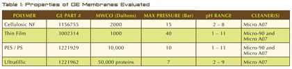
Properties of the four GE membrane polymers are listed in Table 1.
EXPERIMENTAL
1. Materials and reagents
a. GE Osmonics SEPA CF II filtration unit (GE Water & Process Technologies);
b. Wanner Engineering Back Pressure Relief Valve (Wanner Engineering, Inc.; Part No. 111-706);
c. Power Team SPX Hydraulic Hand Pump (SPX Corporation, Model A, 1000 psi);
d. Wanner Engineering Hydra-Cell P200 Metering Pump (Wanner Engineering, Inc.);
e. SEPA CF TF (thin film) NF membrane (GE’s Water & Process Technologies, Part No. 3002314);
f. SEPA PES UF membrane (GE’s Water & Process Technologies, Type: PW, Part No. 1221929);
g. SEPA CF Ultrafilic UF membrane (GE’s Water & Process Technologies, Type: MW, Part No. 1221962);
h. SEPA TF (thin film) NF membrane (GE’s Water & Process Technologies, Type: CK, part No.1156755);
i. Synthetic oil emulsion: P-80® Rubber Lubricant Emulsion (International Products Corp., Lot#130808);
j. Micro-90 Concentrated Cleaning Solution (International Products Corp., Lot# 140303);
k. Micro A07 Citric Acid Cleaner (International Products Corp., Lot# 130205);
l. Anhydrous calcium acetate (Lot# J18Q096, Alfa Aesar – a Johnson Matthey Company);
m. Graduated cylinders (100 and 10 milliliters);
n. Distilled water (Eagles Peak Spring Water, Inc.);
2. Set-up
a. Set-up of the GE Osmonics SEPA CF II filtration unit system is shown in figure 1.
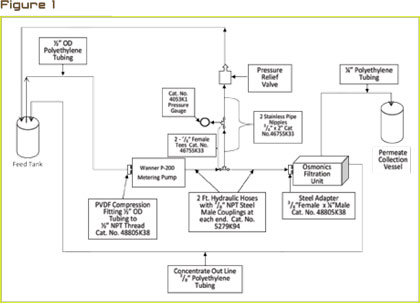
Figure 1: Set-up of the GE Osmonics SEPA CF II filtration unit System (cited from a report done by Al Gabbianelli, chemist; International Products Corporation).
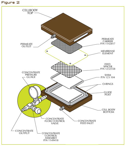
Within the filter cell is a 75 mil (2 millimeter) cavity. Two stainless steel shims of 5 mil and 2 mil were placed in the bottom half of the cell cavity. A 65 mil foulant spacer was placed on top of the two steel shims. The filter membrane with its shiny side downwards was placed over the high foulant spacer by using the four guide posts protruding from the bottom half of the cell for proper positioning. A permeate carrier was then placed on the top half and then rinsed with distilled water. The top half of the cell was mounted to the bottom half using the guide posts for proper alignment. The designated pressure for each respective membrane was obtained using the hydraulic hand pump. The pressure seals the filtration cell and holds it in place.
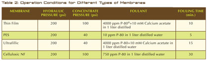
The hydraulic pressure and concentrate pressure used for different membranes are summarized in Table 2 as well as the foulant type and fouling time. The recommended pressure ranges of each membrane were followed. The foulant types and the fouling time were selected on the basis of the needed degree of fouling.
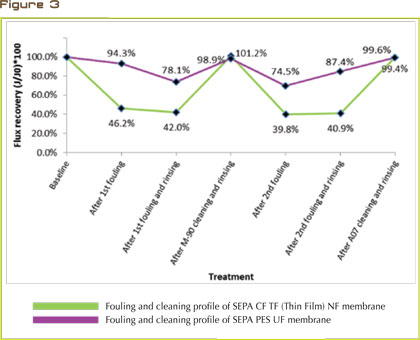
Figure 3: Fouling and cleaning profile of SEPA CF TF (Thin Film) NF membrane and of SEPA PES UF membrane.
The foulants and fouling time varied according to the different membranes. The general procedure for all the tests was:
- Circulate with 2 liters distilled water for 15 minutes to remove any preservatives.
Record the filling time to a pre-established volume (used for calculating J0). - Foul and record the filling time.
- Rinse with 12 liters of distilled water and record the filling time.
- Clean with 2 percent of Micro-90 and/or Micro A07 (40 grams of a cleaner in 2 liter of distilled water). Repeated this whole process if both cleaners were used. The
- Cellulosic NF and Ultrafillic membranes were only cleaned with Micro A07 because of their narrower pH range (Micro-90 has a maximum pH value of 9.8).
- Rinse with 16 liters of distilled water and record the filling time.
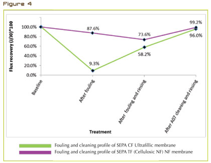
Figure 4: Fouling and cleaning profile of SEPA CF Ultrafillic UF membrane and SEPA TF (Cellulosic NF) NF membrane.
RESULTS AND DISCUSSION
The flux of a membrane was calculated using the following equations:
Flow (milliliters / minute) = Permeate volume in milliliters / (drain time in seconds / 60 seconds / minute).
Flux (gallons / square feet / day) = Flow (ml / min) x 1440 (minutes / day) / 0.1514 square feet Filtration Area /3785 (mil / gallon).
Recovery of flux (J/J0)*100 =the ratio of a flux after a treatment to the original flux (NOTE: The effective filtration area of the GE Osmonics SEPA CF II unit is 5.71 by 3.82 inches or 0.1514 square feet).
In figure 3, a profile of the fouling and cleaning process of the proprietary thin film membrane is displayed. The synthetic oil emulsion and calcium acetate mixture was recirculated for ten minutes in order to sufficiently foul the membrane. Since this membrane tolerates pH values between 1 to 11, both Micro-90 (pH 9.6) and Micro A07 (pH 3.0) were evaluated. Both cleaners restored the flux rate to baseline.
The PES membrane was easily fouled after 5 minutes of recirculating a 10 ppm concentration of the synthetic oil emulsion in distilled water. This quick fouling is likely a result of the larger pore size (MWCO dextran: 10 K) absorbing and subsequently trapping the emulsified oil. However, both Micro-90 and Micro A07 were effective at cleaning the emulsified oil from the PES membrane. Micro-90 and Micro A07 returned 98.9 and 99.6 percent flux recoveries, respectively.
The large pore size (MWCO: 50 K protein) of the Ultrafillic membrane required 15 minutes of recirculation in order for the synthetic oil emulsion and calcium acetate mixture to foul it. Because this membrane cannot tolerate pH values above 9.0, MICRO A07 was the only cleaner used. MICRO A07 achieved a flux recovery of 96.0 percent, which is significant given the low flux after fouling was 9.3 percent.
The Cellulosic NF membrane required 30 minutes of recirculating the synthetic oil emulsion at 750 parts per million in order to sufficiently foul it. The difficulty to foul this membrane may be related to its nano-sized pores; the particle size of the synthetic oil emulsion was too large to be entrapped in the pores. The subsequent cleaning and rinsing with Micro A07 proved effective to restore the flux back to 99.2 percent of the original. ■
About The Author
Jennifer Sun, PhD, is a research scientist for International Products Corporation and can be reached at jsun@ipcol.com. For more information or free samples for testing, call 609.386.8770, email mkt@ipcol.com, or visit www.ipcol.com.
MODERN PUMPING TODAY, September 2014
Did you enjoy this article?
Subscribe to the FREE Digital Edition of Modern Pumping Today Magazine!