Part 1 of this 4-part series on “Mechanical Seal Energy Audits and their Value” laid the groundwork for presenting the topic and its implied theme to an industrial user. The previous part highlighted how certain piping plans deployed on pumps can be an important component to review in an energy management program. Process fluids contained by sealing devices, such as mechanical seals require a fluid to separate a stationary seal face from a rotating face. Without this thin fluid layer the opposing faces could not possibly survive long. However, the fluid layer can be applied in many different ways and some application methods (“flush plans” or “piping plans”) are more cost-effective than others. But reliability improvements are sometimes difficult to quantify.
In contrast, the superior energy efficiency of advanced flush plans and water management schemes can be proven with very high accuracy. Part 2 explains how and why piping plans can have a drastic impact; it shows how the resulting cost savings can be displayed in a well-structured audit.
GETTING THE WHOLE PICTURE
Quantifying energy losses is part of getting the whole picture. Quantifying energy usually involves temperatures. Reading and graphically representing these temperatures is made easy with thermography.
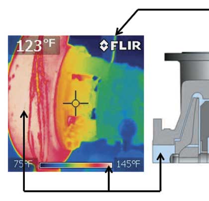
Figure 1
The thermo-graphic image in figure 1 is for API Plan 32. The temperature scale shows the difference between the process temperature and the injected seal water. If the process contains water and the final product is paper, the water must ultimately be removed. And regardless of how the water is squeezed out or evaporated, energy will be consumed. In one particular pulp and paper manufacturing process seal water is injected at 80 degrees Fahrenheit (26.66 degrees Celsius) (see figure 1). The camera is targeted at the seal chamber; it records a temperature of 123 degrees Fahrenheit (55.56 degrees Celsius). This temperature is less than the process; the temperature reduction is caused by the 80 degrees Fahrenheit (26.66 degrees Celsius) water injected through the API 32 piping plan as illustrated in the graphic. This seal water must ultimately be reheated to 145 degrees Fahrenheit (62.78 degrees Celsius). This means much energy is consumed by this reheating.
The Fluid Sealing Association (FSA) working in concert with the European Sealing Association (ESA) created a Life Cycle Cost Estimator tool; it greatly facilitates determining the cost of energy and can be accessed at www.fluidsealing.com (see reference 1). Supplementary information will be found in reference 2.
The essence of compilations by FSA/ESA and other published references is summarized in just three points:
- Although fulfilling the original design intent and functioning as intended, many “traditional” sealing systems found in industrial applications are extremely wasteful of energy.
- For at least the past two decades, totally self-contained sealing systems have been available. Advanced systems can supplant energy wasting flush plans which, although inexpensive when first commissioned, result in cooling and diluting the process. These old approaches require re-heating and in certain applications downstream separation through evaporation.
- Today’s advanced self-contained water management systems are superior to other approaches from life-cycle cost points-of-view. These advanced systems should be considered when designing a sealing system.
Energy cost is the frictional energy consumed by the seal or packing. It is also the pump heat soak, and includes the energy consumed in additional downstream processes to remove flush-to-process dilution and/or restore process temperature. Note that the actual example cited here pertains to the thermographic image in figure 1 for Plan 32. The application or service had a seal water injection temperature of 80° F and process temperature of 145 degrees Fahrenheit (62.78 degrees Celsius). For these conditions the calculation predicted energy losses of 38.145 kW due to heat soak. According to FSA/ESA Life-Cycle Cost Estimator/Version 4.1 (see reference 1) and using the built-in program defaults, this equates to an energy cost of $33,293/year per application.
It is important to have a full perspective on the energy impact of friction; the direct power consumption is $130 for a single mechanical seal and $1,298 for mechanical packing. This compares to the heat soak of $33,293; in other words the heat soak factor is 256 times greater than the direct power cost of a single seal. There is thus real benefit in performing relatively accurate energy cost calculations.
Reliability considerations, however, involve knowing the quality of the seal water system. The needed quality assessment in an audit would, therefore, include an optional lab sampling and testing of the client’s seal water. The findings need to be compared with industry standards for seal water cleanliness. Where optional seal water sampling is requested, a copy of the chain of custody and report analysis would be provided by a competent and diligent audit provider.
ALTERNATIVES TO EXCESSIVE FLUSH INJECTION
A well-structured audit also seeks to determine if the deployment of alternative technology, such as flow meters, might allow reducing the amount of water injected. It should be noted, however, that keeping the original Plan 32 and merely reducing the rate of flush water injection will tend to compromise seal life. It can be reasoned that operator vigilance must be heightened so as to more closely control (and verify) that reduced water injection rates are not causing seal failures. If no such assurance is possible, heat removal could suffer and evaporation and steam formation in the sealing environment may occur. Demands for increased operator vigilance and/or narrowing the allowable pump seal environment range will increase the risk of incurring equipment downtime and process outages.
In its published references FSA further comments on API Plan 32 flush arrangements and reminds users that the flush fluid must be compatible with the liquid or slurry being pumped. The flush fluid will enter the process and will, in most instances, have to be removed so as to restore process fluid integrity. Actual costs go beyond initial purchase cost or even the costs associated with reclaiming separated diluents. For these reasons, Plan 32 is very rarely recommended today.
Just in case water flush water flow reduction from previously 8 gallons per minute to potentially only 1 gallon per minute per seal could be used as an energy savings option, we refer to figure 2.
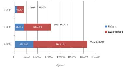
Keep in mind that the various risk factors associated with mere flow reductions are difficult to quantify. However, this graph shows the annual re-heat and evaporation costs (from the AESSEAL Asset Health Software) for an application at 150 degrees Fahrenheit (65.56 degrees Celsius) and steam costs of $5.00/1000 pounds.
Reducing flow from 8 gallons per minute to 1 gallon per minute reduces the energy cost from $62,905 to $7,862/year. While figure 2 highlights the cost savings advantage of flow reduction, we note that even at 1 gallon per minute the relative energy cost is still nearly $8,000 per year. Moreover, the seal flush water would have to be of suitable quality; accordingly, an audit would have to include this quality assessment. Although a client might contemplate reducing flush injection to a mere 1 gallon per minute, acceptable water cleanliness would have to be ascertained.
The Safematic Division of the John Crane Company manufactures a seal water filtration system. Safematic® recommends the following seal water standards (see reference 4):
- No Impurities, such as clay, smaller than 10 micrometers
- No particles larger than 50 micrometers
- No more than 10 milligrams of silicate content per liter
- No more than 30 milligrams of organic impurities per liter
- No more than 1 milligram of iron per liter
- The total water hardness should be lower than 10 degrees dH (medium hardness)
Non-filterable residue relates to the total suspended solids (TSS), the dry-weight of particles that passed through filtration. The practicality of filtration relates to flow and demand for seal water consumption. Filtration below the 50 micron capabilities of a reliable system such as the John Crane Safematic Seal Water Filtration System would be ideal. High demand increases the load on the filtration system. Achieving 1-micron filtration improves seal water quality, however, this becomes challenging with continuous flow demands.
The point is that Plan 32 can be replaced by a support system that does not use injected seal water. Not having to inject seal water would take issues of water quality out of the risk equation. Dispensing with water issues will add great value as long as consideration is given to the lifecycle cost in terms of equipment reliability. That said, our article now gravitates towards technology options available to achieve low (0.11 gallons per minute) to perhaps even zero flows (0 gallons per minute). The seal energy audit must deal with how much flow is needed and what is the optimum water quality specification.
How is flow used to cool and clean the seal area? As previously outlined, API Plan 32 is the injection of water (or a clean fluid) into the seal chamber. This injection is commonly referred to as a flush injection. The term flush implies that the fluid injected at a higher pressure is used to keep the mechanical packing and/or mechanical seal clean and cool. As referred to in Annex G of API-682, 4th Edition, Plan 32 is not recommended for only cooling purposes. What about for cleaning purposes—how much flush is required to keep the seal chamber clean to optimize seal and packing life?
The Hydraulic Institute Rotodynamic (Centrifugal) Slurry Pumps–HI/ANSI Standard 12.1-12.6-2011 (see reference 4), elaborates on the use of single mechanical seals and seal chamber design in section 12.3.8.3.8. The section provides application limits for seal types relative to concentration percentage by volume, specific gravity and average d50 particle size. Definition is provided for split-non-pusher design, rotating elastomeric bellows, stationary elastomeric bellows and heavy-duty slurry designs.
The information relates to the use of single seals only. The HI/ANSI Standard (see reference 4) provides a useful table, giving guidance on the selection of single seals (depending on the characteristics of slurries being sealed) when no external injection is used. When an external flush injection is chosen, the concentration of the pumped slurry and allowable particle size ranges are only limited by the ability of the injection system to exclude the slurry from the seal chamber. However, the associated product dilution needed to accomplish this task must be assessed and considered by the user (see reference 2).
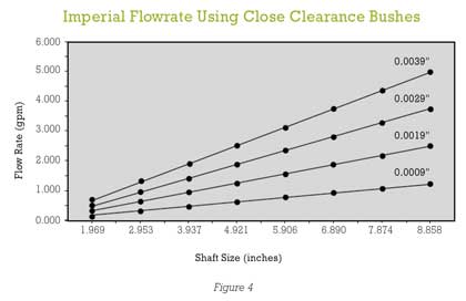
Again referring to this standard (Table 12.3.8.3.8a, see reference 3), the flow in US gallons per minute and liters per minute is matched to the seal shaft size and the radial clearance of a bushing mounted in the bottom of the seal chamber (figure 3). This illustration shows the radial clearance restriction required between the throat bushing and the rotating shaft.
The restriction is placed just behind the impeller and the flush at the single seal is injected from the right side of the illustration.
The recommended flow to exclude slurry from the seal chamber is expressed as a velocity, specifically 4.6 meters per second or 15 feet per second as it flows past a bushing. Tables often convert this to a volume flowrate (gallons per minute). For instance, a 2-inch shaft with 0.020-inch radial clearance requires 6 gallons per minute.
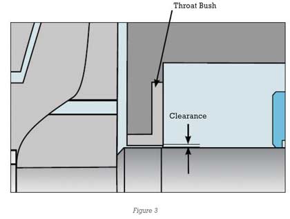
The general relationships between the flowrates, shaft sizes and bushing clearance dimensions identified in figure 3 are displayed in figure 4; they were obtained from the AESSEAL Seal Engineering Handbook. In order to reduce this flow and still maintain a flow velocity in the range of 5 meters per second, the HI/ANSI standard and the AESSEAL Handbook agree on the following radial bushing parameters:
The use of Plan 32 water injection to exclude slurry (process) from the seal chamber requires a .004-inch bushing clearance on a 2-inch shaft with reduced flow of less than 1 gallon per minute. Reducing the flow without a restricting throat bushing means the flush injection is not an effective method to flush the process fluid away from the sealing device for cleaning purpose. This applies to mechanical packing as well as mechanical seals. Wear, temperature, erosion and corrosion impact the radial clearance. If these factors cause the clearance to increase, the velocity (flow) should be increased to provide the recommended velocity referenced in the standard.
A LOOK AHEAD
That, then, is a perfect lead-in to the next part. Part 3 will elaborate on why—and how—zero water is consumed in suitable and readily available water management systems. Using the above cost calculations and technical explanations greatly facilitates establishing the cost-justification for these systems. Closed water management systems from competent vendors are mature and highly reliable products. They have replaced API Piping Plan 32 in several thousand installations.
REFERENCES
- FSA/ESA Life-Cycle Cost Estimator–Version 4.1, Tab Flush Plans.
- “What Is the Sealing System Energy Footprint for Removing Diluents from the Process Stream,” Pumps & Systems, October 2010, p. 51.
- See the John Crane website: www.johncrane.com.
- HI/ANSI Standard 12.1-12.6-2011, pp. 75-76; Hydraulic Institute Standards, (2011).
- American Petroleum Institute, “Pump-Shaft Sealing Systems for Centrifugal and Rotary Pumps, API Standard 682, Fourth Edition, May 2014, p. 198.
About The Author
Tom Grove is an executive vice president at AESSEAL Inc., one of the world’s leading specialists in the design and manufacture of mechanical seals and support systems. He can be reached at tom.grove@aesseal.com. Heinz P. Bloch, P.E., is one of the world’s most recognized experts in machine reliability and is a Life Fellow of the ASME, in addition to having maintained his registration as a Professional Engineer in both New Jersey and Texas for several straight decades. As a consultant, Mr. Bloch is world-renowned and value-adding. He can be contacted at heinzpbloch@gmail.com.
________________________________________________________
MODERN PUMPING TODAY, November 2015 Buyers Guide
Did you enjoy this article?
Subscribe to the FREE Digital Edition of Modern Pumping Today Magazine!