Energy Management is critical to operational efficiency. Reviewing energy use in each link of the supply chain of a business can produce significant benefits. Increasingly, industrial companies are making a commitment to energy control by staffing energy management positions. These positions may even be referred to as the “Corporate Energy Czar”. The International Standards Organization recognizes the importance of energy management in the ISO-50001 Standard for Energy Management Systems.
Mechanical seals are energy consumers. They are components which prevent fluid leakage from the shaft region of process pumps and other rotating equipment. The vast majority of mechanical seals are deployed in process pumps at refineries, petrochemical plants, pulp and paper plants and a host of other industries. With the exception of gas-injecting seals (available on very few pumping services), all other mechanical require a flush liquid in the seal cavity. This flush liquid can be supplied in different quantity and at different pressures so as to carry away heat and provides the separating liquid needed between seal faces. Many mechanical seals have served their respective users, but technology updates will prove quite revealing to some.
OBJECTIVES OF MECHANICAL SEAL ENERGY AUDITS
The objective of periodic audits is to point out and quantify the monetary value of installing modern products. Doing so will, in some cases, reduce or avoid downtime and maintenance expenditure. In other instances, the audit can detail energy improvement opportunities associated with alternative flush liquid application plans. In the pulp and paper industry seal water piping plans deserve special attention. The focus is on the cost of reheating and/or evaporation of seal water, if the seal water is injected into the process stream. The cost to reheat and further evaporate this injected seal water can be eliminated by using the right flush plan. Technology exists to eliminate injected seal water.
The second objective is to describe in detail the American Petroleum Institute (API) Seal Piping Plan specifications and summarize how each plan is deployed on the equipment. The selection of the API Piping plan can prolong the life and reliability of the equipment; however, this can also have a significant impact on energy usage and energy efficiency.
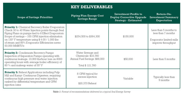
Using a concise survey form, a major and highly innovative mechanical seal manufacturer physically inspected each piece of equipment and documented as much information as was available. The data elements included the seal arrangement, the seal piping plan and the process temperature. Because it is critical to dovetail the energy saving solution with improvement in equipment reliability, additional data was gathered. This included seal operating temperatures to measure piping plan efficiency as well as benchmarking the seal water quality using laboratory analysis. The mechanical seal manufacturer explained the scope of the savings opportunity in a “Statement of Key Deliverables”: The key deliverable is to identify the cost and provide all of the technology options to set a strategy for improvement. The deliverables are separated into priorities (see Table 1).
AUDITS START WITH EXPLAINING API PIPING PLANS
A mechanical seal audit starts with listing and explaining the API Piping plans deployed on the equipment at a particular plant. Although “API” refers to the industrial standards issued by the American Petroleum Institute, the mechanical seal and compression packing details of non-API compliant centrifugal pumps will be similar. In all cases graphically depicting the approximate cross-section of a pump in relation to the mechanical seal region will be helpful. For the sake of uniformity, the suction flange for the process fluid is shown on the left. Accordingly, the impeller is mounted on the left end of the shaft and the discharge flange is shown at the top. While the impellers are shown with balance holes to “balance” the pressures to the left and to the right of the suction eye, not all impellers or services will require this balance. The seal chamber (stuffing box) is depicted with a mechanical seal in place.
The audit replicated in this four-part series of articles assumes that the plant started out with API Seal Flush Plans 02, 11, 23 and 32. The audit explains alternatives such as Plans 53A and 54.
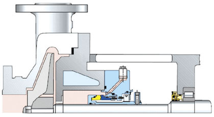
Figure 1: API Plan 02
Figure 1 shows API Plan 02, a dead-ended seal chamber with no flush fluid being injected into the process. There is no auxiliary piping connected to the mechanical seal cavity (shown) or the stuffing box, in case braided packing is used. This plan is suitable for sealing cool clean fluids with high specific heat, such as water, in relatively low speed pumps. Figure 1 shows a jacketed cooling (or heating) cavity for occasional applications favoring controlled seal chamber temperatures.
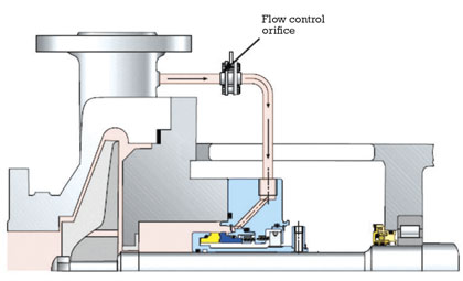
Figure 2: API Plan 11
In Plan 11 (figure 2) product is recirculated from the discharge of the pump to the seal through a flow control orifice. This arrangement is selected to increase the pressure at the seal to the full discharge pressure of the pump. The plan maintains pressure above vapor pressure; the product is less likely to vaporize at elevated pressures.
If the product is abrasive, care must be taken to prevent erosion at the seal faces where the recirculation line enters the seal. Plan 11 is used on condensate and hot water applications. Here, the additional heat generation created by the seal faces could cause vaporization. Traditional seals will fail if a vapor replaces the sealing liquid.
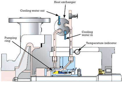
Figure 3: API Plan 23
Product is re-circulated, in Plan 23 (figure 3) from the seal chamber to a heat exchanger and back to the seal chamber. Circulation is created by a pumping ring in the rotating seal assembly. This plan is used in hot and clean services, e.g. boiler feed water. Plan 23 is more efficient than the alternative Plan 21 because the cooled process around the seal is re-circulated. Plan 21 (not depicted) connects a line from the pump discharge through a heat exchanger and into the seal. This creates flow of the cooled process fluid, which must be reheated as it re-enters the process.
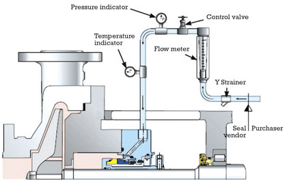
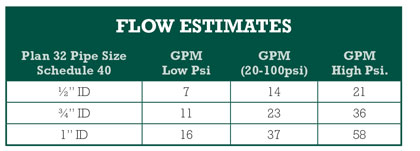
Figure 4: API Plan 32
Plan 32 (figure 4) consists of the injection of a clean or cool liquid from an external source directly into the seal chamber. This is selected for duties with dirty or contaminated fluids, high temperature applications, polymerizing and oxidizing fluids or media with poor seal / mechanical packing lubrication properties. Plan 32 is used on mechanical packing and single mechanical seals.
From an energy point of view, this plan is the most costly to operate. The seal water used for injection at a particular site must be known to proceed with the audit. As the plan illustrates, a control valve and flow meter control the volume of water injected. These controls are frequently removed because of clogging if the seal water quality has particulates.

Figure 5: API Plans 53 and 53A
Plan 53A as shown here is the conventional layout found in the API specification. Plan 53 applications are an adaptation from this traditional plan. Plan 53 is a pressurized barrier fluid circulation system for a dual seal configuration. It is used to control the fluid film formation between the inner seal faces in order to extend life.
Plan 53 differs from Plan 52 in that the secondary medium in Plan 52 is called a “buffer” fluid. A Plan 52 system has the buffer at a lower pressure than the seal chamber pressure and the fluid film at the inner seal face set is the process fluid. A Plan 53 operates with a “barrier” fluid at a pressure higher than the seal chamber. This means the barrier fluid is the fluid film at the inner seal face set.
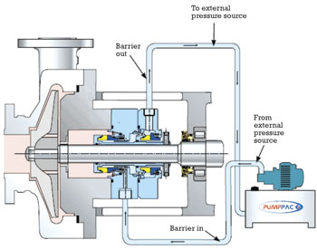
Figure 6: API Plan 54
The “buffer” verses “barrier” fluid terminology is an important distinction. This distinction applies to the way a Plan 54 (figure 6) system is set-up. This plan is a pressurized external barrier fluid circulation from a central source by a stand-alone pumping unit.
From experience, the term Plan 54 is applied broadly and collectively. This may take the form of a pressurized water to drain system or it may be a closed loop system for a single or multiple applications.
WATER-TO-DRAIN ARRANGEMENT
Illustration A depicts a water-to-drain arrangement. A common header is fed by a seal water pump. Supply lines from the header connect to the pump seal inlet port and go to a drain through the seal outlet. Flow is not recovered or re-used.
Pressure is not consistently applied to each pump due to piping friction losses and flow diversion.
If the primary supply pump to the seal water system is lost, multiple seal failures could occur. The seal pressure at each seal can be reduced, if needed. Such pressure reductions are needed in installations where the header labeled “Alternative Flow” must also satisfy higher pressure requirements, such as wash-down water.
If the Plan 54 re-captures the seal water after it exits the seal and recycles this water, product contamination does occur.
A LOOK AHEAD
A comprehensive audit may include a seal water sample analysis performed by an independent laboratory. Such sampling and analysis is occasionally requested by the plant, but would incur an optional charge. Contaminated barrier fluid systems limit the reliability of the sealing system in a Plan 54 arrangement. Part 2 of this series will highlight the energy impact of using API Plans at one particular pulp mill.
About The Author
Tom Grove is an executive vice president at AESSEAL Inc., one of the world’s leading specialists in the design and manufacture of mechanical seals and support systems. He can be reached at tom.grove@aesseal.com. Heinz P. Bloch, P.E., is one of the world’s most recognized experts in machine reliability and is a Life Fellow of the ASME, in addition to having maintained his registration as a Professional Engineer in both New Jersey and Texas for several straight decades. As a consultant, Mr. Bloch is world-renowned and value-adding. He can be contacted at heinzpbloch@gmail.com.
____________________________________________
MODERN PUMPING TODAY, October 2015
Did you enjoy this article?
Subscribe to the FREE Digital Edition of Modern Pumping Today Magazine!