

A goal of piping system design is for the system to maintain continued operation over its life cycle with minimal maintenance. Degradation or failure of pumps and components or development of pipe restrictions can disrupt or degrade system operation. Taking the system offline and replacing or repairing the compromised hardware can remedy some problems, such as a broken valve. However, when the location of the problem is not apparent or testing to find the problem could be complex or costly, engineers and engineering management must develop other approaches and resources to finding the problem source.
HOW TO DIAGNOSE PIPING PROBLEMS
Consider degraded operation in a system containing significant amounts of underground piping. One solution might be to run inspection equipment, such as a pipe camera, throughout the piping system. However, inspection equipment can be expensive or difficult to use depending on the configuration of the system. An alternate approach is to use fluid flow software to create a model of the system and simulate its normal operating conditions. Investigators can benchmark the expected system behavior against actual performance data obtained from the existing plant monitoring equipment and systems. Plant engineers can then create modified models simulating various blockages, leaks, or other forms of failure to compare with the expected and actual plant performance.
Such comparisons can be used to localize or identify the source of the performance degradation. This analysis occurs without physical manipulation of the existing system and can be an economical and timely way to eliminate or limit the amount of physical testing or examination needed to pinpoint the reason for system degradation.
FIREWATER SYSTEM BLOCKAGE
In the case of a chemical plant in Baltimore, alarms indicated a blockage in the underground firewater system was preventing the system from meeting its design requirements. The system consisted of fifty-five firefighting appliances, three electric pumps, and one diesel backup pump. Two city mains supplied water. The firewater system is critical to maintaining safe operation of the chemical plant, so there was a need to promptly find the problems and make repairs to ensure continued plant safety and minimize downtime.
The plant staff could have performed a manual system inspection to find the blockage, but much of the firewater system consisted of underground piping and was not easily inspected. The location of the blockage was unknown, so inspectors might have needed to examine the entire system to ensure all potential blockage locations were cleared. The decision was made to choose an alternate solution, specifically to build a computer model of the system and use this model to perform analyses to locate potential blockages.
The system was modeled using the fluid flow analysis software Design Flow Solutions. There were several steps to the modeling process. The header geometry was assembled, and then details such as pipe specifications, lengths, diameters, valves, fittings, size changes, and elevation changes were input from construction schematics. Flow resistance characteristics were obtained for the fire hydrants making up the system discharge ports. This data was used to create hydraulic components simulating the hydrant performance, and these components were included in the overall system model. Vendor-supplied pump curves provided the data needed to model the performance of the system’s pumps. These pumps were added to the model and could be programmatically switched on and off to quickly test various system configurations. In addition, if needed, the pump characteristics could readily be changed to simulate degraded pump operation. Finally, boundary conditions such as known pressures and flow rates were determined and input into the model.
After building the model, the next step was to evaluate the modeling assumptions in order to determine sources of error. Inherent in any model is some error, and that error can be trivial or significant depending on the scenario. An analyst needs to check that simplifying assumptions does not produce error outside of accepted limits. If necessary, additional data can be gathered or modeling changes made to reduce error or bias the error in the desired direction consistent with the goal of the model usage. Proper evaluation and accommodation of assumptions allow the model to produce sensible and useful results.
In the case of the firewater system, it was determined that the fire hydrants at each discharge were a major source of head loss and had a significant impact on the overall system performance. In light of this fact, engineers performed additional research and located updated data. This updated data was used to modify the resistance information of these components in the hydraulic model.
The resulting model simulated the firewater system under idealized conditions and calculated the expected system flow rates. The model was benchmarked against data representing the acceptable and expected design performance of the system. Engineers then began a series of model modifications and analysis to compare the model results to actual system performance data. The model results allowed engineers to eliminate pump degradation as the cause for degraded system performance and the resulting alarm. Ultimately, additional model output allowed for identification of a failed buried pipe header as the cause of the blockage.
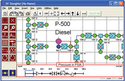
Intake section of the firewater system modeled in Design Flow Solutions
PIPE MODEL BENEFITS
Modeling a piping system has a number of benefits. As in the case described, the computer modeling and analysis enabled plant staff to quickly, and non-invasively, locate the source of performance degradation. The ability of this computer model to locate the blockage allowed the plant staff to focus on the repairs and limit excavation and work to the compromised part of the system. This minimized the scope of the repairs, and thus potentially reduced the cost of the repairs and shortened the plant downtime. The effort spent constructing and analyzing the system model was significantly less than the potential effort of manually inspecting the firewater system.
Another benefit to modeling a piping system is once a model is built and validated, it provides the added benefit of simulating alternate configurations to predict system behavior in emergent conditions. Models can be rapidly modified, whereas physical system tests take time, resources, labor, and other additional costs to perform.
Piping models are also beneficial for quickly resolving emergent system states until a permanent repair can be made. For example, when an unexpected component failure occurs, a pre-validated and functioning model can be manipulated to quickly analyze different system lineups and determine if there is a temporary solution until system repairs can take place.
For existing systems, models are effective analytical tools whether done on paper, through computer spreadsheets, or using an advanced fluid flow software package such as Design Flow Solutions. In the case described here, the computer model of the firewater system proved to be a useful means to economically assist in locating the source of the system blockage without a manual inspection. Models are also critical to the design of new piping systems by ensuring the new system will deliver sufficient flow or pressure. Regardless of how they are used, well-built computer models form a fast and inexpensive tool for solving problems with piping systems. They can reduce the amount of expensive system testing, or they can augment performance testing to minimize costs. ■
_________________________________________________________________________
ABOUT THE AUTHOR
Michael Hollister and Benjamin Jessup are mechanical engineers at ABZ, Incorporated in Chantilly, Virginia. ABZ developed and sells Design Flow Solutions, a software package for solving fluid flow problems. They can be reached at 800.747.7401 or via email at dfs@abzinc.com. For more information visit www.abzinc.com.
_________________________________________________________________________
MODERN PUMPING TODAY, May 2013
Did you enjoy this article?
Subscribe to the FREE Digital Edition of Modern Pumping Today Magazine!
![]()
The Right Tool for the Job
