


Throughout history mankind has relied on rotating shafts and shaft torque to power its society. From an ancient Roman flour mill in Barbegal, France, to the modern nuclear aircraft carrier, the common denominator is the rotation of a shaft generating torque and power. Naturally, measuring the torque and power produced through a shaft-driving system is critical to understanding and optimizing the overall machine or process. This article provides an overview of various torque and power measurement tools including the benefits and limitations of each system.
QUANTIFYING TORQUE AND POWER
Torque is defined as a twisting force that tends to cause rotation. The word originated from the Latin word, torquere, meaning to twist. Torque can also be quantified by the equation (where the lever arm is the perpendicular distance from the axis of rotation to the line of action of the force):
Torque = Force applied x lever arm
Torque is measured in foot- pounds or Newton-meters. Archimedes, the famous Greek mathematician and inventor, was so excited about force and levers he was credited with the statement, “Give me a lever long enough and a place to stand and I will move the world.” One of the most recognizable equations, commonly used by mechanical engineers, is:

- P=Power, units of horsepower
- T= Torque, ft lbs force
- N= Revolutions per minute
- 5252 = Constant
Quantifying torque and power, helped engineers to develop and improve various designs but proper tools were still needed for proper and accurate measurement. A breakthrough concept was developed by Samuel Christie and later, improved and popularized by Charles Wheatstone, became known as the Wheatstone bridge.
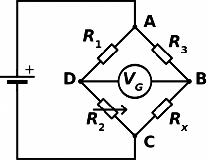
Wheatstone bridge diagram
The significance of the Wheatstone bridge cannot be underestimated. This concept laid the foundation for invention of the strain gage, invented in 1938 by Edward Simmons and Arthur Ruge. Ruge and Simmons, working independently of each other, both discovered that small diameter wires made of electrical resistance alloys could be bonded to a structure to measure surface strain. This type of gauge had the advantage of responding well to static strains. It was due to the demands of this rapidly growing industry that the important advance into foil strain gauges was made.
Combining the concepts of the Wheatstone bridge and strain gage, engineers and inventors were able to develop various types of equipment to accurately measure torque and power. Each has its own advantages and disadvantages but, all rely on established concepts and common goals of monitoring mechanical forces and being instrumental in system improvements.
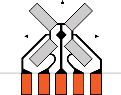
Vishay full bridge general purpose strain gage – shear/torque pattern
DYNAMOMETER
The dynamometer is the most common tool used in the evaluation of torque and power. Dynamometers have the advantages of being very accurate, allowing many types of testing. From a single system to complete vehicle testing, there are many suitable dynamometers for each requirement available.
For all of their advantages, dynamometers, however, are limited by their cost, size and capabilities. Their size limits their capability for tests onboard marine vessels and in tight spaces. In addition, some systems are too large for any type of dynamometer testing.
LOAD CELL AND MOMENT ARM
A simple, yet cost effective torque testing apparatus involves a load cell with a torque arm arrangement mounted to a specific load. As a force is applied to the load, the armature will compress the load cell. From the load cell data and moment arm length, torque information can be calculated.
The disadvantages of such a system relate to the limits of the load cell, accuracy and data collection. The system does not measure actual shaft torque but, rather, forces on a moment arm. The system is also limited by space, flexibility and rarely used on modern marine vessels or large equipment.
ROTARY TORQUE SENSOR
A more modern approach to torque and power data collection is the in-line rotary torque sensor. Rotary torque sensors offer a range of torque ranges, a high degree of accuracy, digital output capability and various types of data collection features, i.e. RPM, shaft direction, in addition to torque and horsepower. Some rotary torque models also have the advantage of withstanding very high RPM (up to 50,000 RPM) and G-Force level. However, inline sensors are costly, do not offer versatility and have torque limitations. They also require shaft modifications before installation. This can be very costly with large diameter shafts.
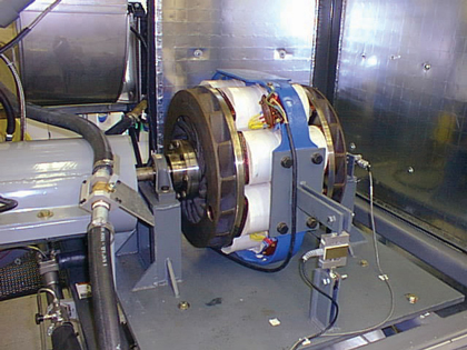
Featured Image: Heavy duty engine dynamometer (photo credit: UC Riverside
Above: Armature and load cell to measure torque (photo credit: Dr. Scott K. Thomas, Wright State University)
RADIO TORQUE TELEMETRY SYSTEM
A very effective and more versatile option for measuring torque and power is the radio torque telemetry system. Typical units are not limited to any torque level and can be used on, or specified for, nearly any shaft diameter. They also offer the advantages of reasonable pricing, easy calibration, portability and convenient installation (no shaft modifications required).
There are limitations with radio torque telemetry systems that must be considered. Shaft rotational speed is critical information to have due to the mechanical limits of rotating components, i.e. battery, adhesive tape, and so on. Occasionally, radio interference from adjacent devices can pose torque system operation challenges. Proper strain gage application, required for successful system operation, can be tedious. Improperly installed strain gages can result in accuracy and data errors.
Binsfeld Engineering Inc. produces a selection of non-contact torque and power measurement systems for both temporary and permanent applications. Binsfeld TorqueTrak radio telemetry systems offer all the benefits described here including convenience, versatility and reasonable pricing as well as user-friendly operation. BEI also provides friendly and immediate technical support for any system issue.
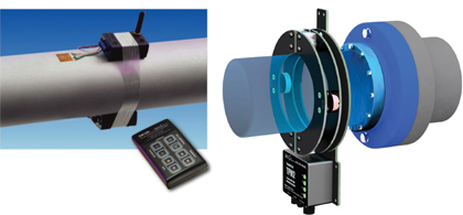
TorqueTrak 10K radio torque telemetry system
SUMMARY
Understanding theories of torque, power and test equipment can benefit in the search for a torque telemetry system. As there is no perfect solution, understanding the limitations of each system provides insight to choosing the best and most cost effective option. ◆
Brian Carr is the U.S. sales manager for torque telemetry systems at Binsfeld Engineering Inc. Brian earned a BSME at Michigan Technological University and an MSBA from Boston University and has been selling torque measurement systems for over three years. He can be reached at brian@binsfeld.com. For more information, visit www.binsfeld.com.
____________________________________________
MODERN PUMPING TODAY, August 2015
Did you enjoy this article?
Subscribe to the FREE Digital Edition of Modern Pumping Today Magazine!
![]()